
User guide for the Millworker add-in for Autodesk Inventor 2026 and 2027
Edition November 2026
Getting started
 Getting started
What Millworker is, what it needs, and a first joint in five minutes.
Millworker adds a Millworker tab to the Inventor ribbon with tools for millwork and cabinet panels. You model a cabinet or a piece of furniture as solid bodies in one multi-body part, and Millworker joins, drills, grooves and shapes those bodies for you. In the assembly made from that part, Millworker marks edgebanding and grain, assigns the shop's materials, places hardware and prints cut lists and bills of materials.
What you need
| Inventor | Autodesk Inventor 2026 or 2027 (one Millworker install serves both). Inventor 2025 and older cannot load it. |
| Windows | Windows 10 or 11, 64-bit. |
| Units | Works in inches by default; millimetres can be chosen in Millworker Settings. |
| Shared data | Optional: a shared folder for the material database, so every PC in the shop uses the same materials, edgebands, profiles and hardware. |
Where the tools are
The Millworker tab shows the panels that fit the document you are in. See The Millworker ribbon for the full map.
- In a part: Settings, Joins, Fasteners, Features, Treatment and Tools.
- In an assembly: Settings, Panel Marking, Materials, Hardware and Tools (and NestCAM, when it is installed).
- In a drawing: there is no Millworker tab.
Your first joint
- A new part (Standard (in).ipt) with two 3/4″ boxes as separate solid bodies: a cabinet side standing up and a bottom butting against it.
- On the Millworker tab, click Dado Join (Joins panel).
- Click the bottom (the body to extend). It lights up.
- Click Face… in the mini toolbar, then the inside face of the side.
- A see-through red preview shows the dado. Type a Depth or keep
MW_DadoDepth(1/4″). - Click OK. The dado is cut, the bottom runs into it, and a DadoEdge1 node appears in the model browser.
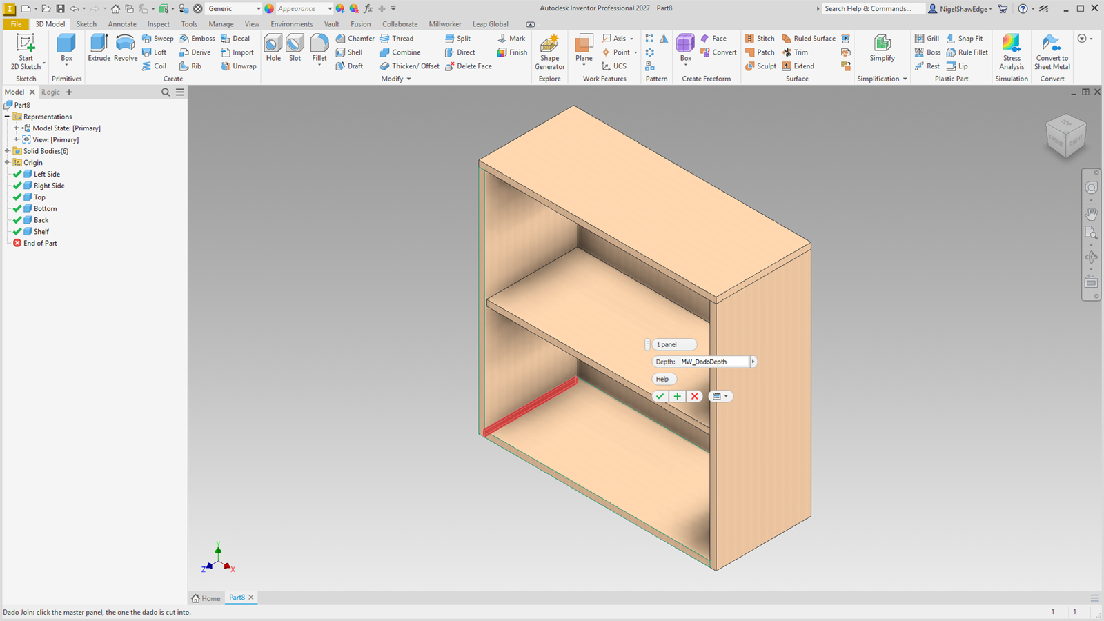
Double-click DadoEdge1 in the browser to change it. Every tool works this way; read How the tools work next.
Install and update
Install Millworker, switch it on in Inventor, and where its files are kept.
Install
- Close Inventor completely.
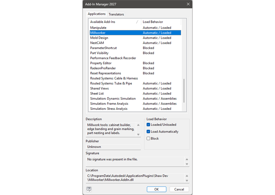
- Run the Millworker installer [installer name and download link to come with licensing]. It puts the add-in in
C:\ProgramData\Autodesk\ApplicationPlugins\Shaw Dev\Millworker\, where Inventor 2026 and 2027 both find it for every Windows user on the PC. NestCAM and CabinetCAD go beside it inShaw Dev\NestCAM\andShaw Dev\CabinetCAD\, and their settings and logs are kept inShaw Dev\Data\, so installing again never touches them. - Start Inventor. The Millworker tab appears on the ribbon when a part or assembly is open.
Update
Close Inventor, run the new installer, and start Inventor again. Inventor locks the add-in's files while it runs, so an update cannot go in while Inventor is open. Your settings and data are kept.
Where Millworker keeps things
| What | Where |
|---|---|
| Settings | C:\ProgramData\Autodesk\ApplicationPlugins\Shaw Dev\Data\Millworker\settings.json. NestCAM and CabinetCAD read it from there, and keep their own in Data\NestCAM and Data\CabinetCAD. |
| Error log | C:\ProgramData\Autodesk\ApplicationPlugins\Shaw Dev\Data\Millworker\error.log: send it with any support request. |
| Materials, edgebands, finishes, veneers | Millworker Materials.db and its Images folder, in the material database folder (Settings). |
| Edge profiles | Millworker Edge Profiles.json, next to the material database. |
| Formula functions | Millworker Functions.json, next to the material database. |
| Hardware library | Millworker Hardware.json and the Millworker Hardware stand-ins folder, next to the material database. |
| Marks, nodes, formulas | Inside each part or assembly file, as attributes: they travel with the file. |
 Licence, trial and buying
The 7-day trial, buying Millworker and its add-ons, signing in on another computer, and moving a licence.
Millworker runs free for 7 days on each computer, then needs a licence. The licence is checked with the licensing service at licensing.inventor-addins.com each time Inventor starts. Everything about it is under the Licence button on the Settings panel.
The trial
- The trial starts the first time Inventor loads Millworker on a computer. Nothing to enter.
- While it runs, the Licence button reads Trial: 5 days (the days left), and a reminder with a Buy button shows once Inventor has started.
- When it ends the button reads Trial ended. Clicking any Millworker tool then offers to buy or sign in. Your files and settings are untouched.
Buy
- Click Licence, then Buy (or Buy in the trial reminder).
- Choose the number of seats and any add-ons, and enter your email. Signed in already, you are only offered what you don't have yet.
- Pay on Stripe's secure page in your browser. Millworker waits, and turns the licence on by itself as soon as the payment goes through. A receipt is emailed to you.
A seat is one person on up to two computers (say, work and home). The buyer gets the first seat. With more seats, give the others to your staff in your account at account.inventor-addins.com.
Sign in on another computer
- Install Millworker on the other computer and start Inventor.
- Click Licence, then Sign in, and enter the email the seat is assigned to.
- Type the 6-digit code that is emailed to you (look in junk mail if it hasn't arrived). Millworker is licensed on this computer too.
There is no serial number to type: your email is your licence.
Move to a new computer
- On the old computer: Licence → Deactivate. Its place is free for another computer.
- Old computer gone? Sign in to your account at
account.inventor-addins.comand free it there (up to 3 computers per seat every 30 days).
Add-ons
NestCAM (with Cut List), CabinetCAD, Parametric Panels, PhotoGroove, Veneer Match and Drawer Box are add-ons on your Millworker licence. Clicking a tool of one you don't have offers to buy it; it is turned on straight after payment, on every computer the seat is used on. Add-ons can be bought for fewer seats than Millworker; your account's admin then gives them to the people who need them.
Offline, and new versions
- Millworker keeps working without internet for up to 14 days after its last check. Connect once in that time to carry on.
- When it checks your licence, Millworker sends this computer's name, its Millworker version and how often you use each tool. The licensing service also records the country you connect from (worked out from your internet address). Nothing from your drawings or files is sent.
- A licence is for the major version you buy (and one released within 120 days of buying). A yearly upgrade brings a new major version to Millworker and every add-on you own; buy it from your account.
C:\ProgramData\Autodesk\ApplicationPlugins\Shaw Dev\Data\Millworker\Licences, where NestCAM and CabinetCAD read it too.The Millworker ribbon
Which panels show in parts, assemblies and drawings, and what each tool is for.
The Millworker tab changes with the document. Settings is always the first panel.



Add-on products. NestCAM, Cut List, CabinetCAD and Veneer Match are separate products that run on top of Millworker. They need Millworker installed and licensed, add their own panels or buttons to the Millworker tab, and each has its own help, opened from its own Help button.
How the tools work
Mini toolbars, picks, see-through previews, Apply and OK, and the Millworker node each tool makes.
Every part tool works the same way, so once you know one you know them all.
The mini toolbar
Starting a tool opens a small toolbar beside the model. It is stacked: one value to a row, with buttons on rows of their own, so it never runs across the screen.
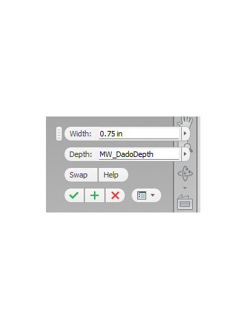
- Next pick: the label with a pointer says what to click next.
- Value boxes show their name inside (Width:, Depth:…). They take a number, an expression or a parameter name; the arrow lists the part's parameters.
- Buttons such as Settings…, Flip, Swap, Rotate 90° and Clear show icons.
- X, Y, Z toggles in red, green and blue choose a direction; the pressed one is in use.
Pick, preview, commit
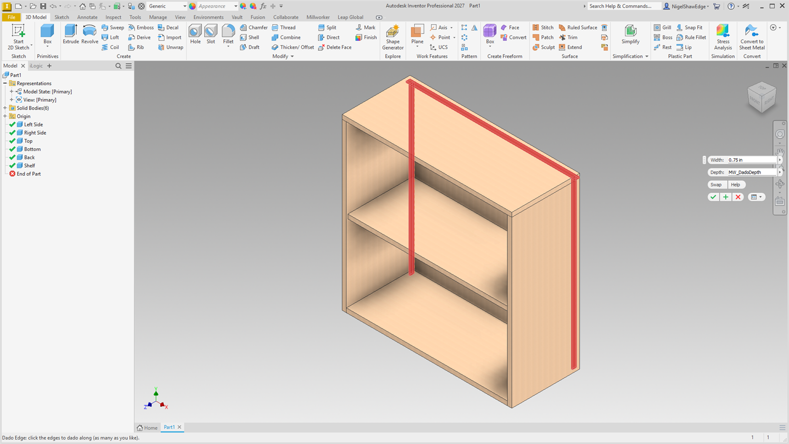
- Pick what the label asks for. Click a picked item again to take it back. Most tools take as many picks as you like.
- A see-through preview shows what will happen: red for material taken away, orange for extras such as CAM corners, blue for new bodies. It is drawn on top of the model, so you see a cut even inside a panel, and it follows each value as you type.
- Apply makes it and keeps the tool running for the next joint. OK makes it and closes the tool. Cancel or Esc drops the preview and makes nothing.
Each Apply or OK is one undo step.
The Millworker node
What a tool makes is grouped into one node in the model browser, with the tool's icon and a name such as DadoEdge1 or Dowels3. Double-click it to change it: see Editing a Millworker node.
Editing a Millworker node
Double-click a node to open its tool again with its picks and values, change them, and remake it in place.
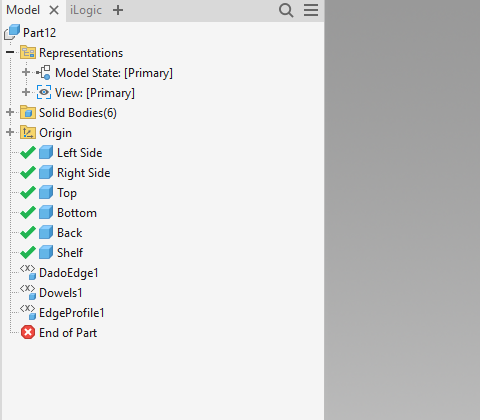
- A part with a Millworker node in the model browser.
Double-click a Millworker node, or right-click it and choose Edit Millworker Feature.
Tools that open again
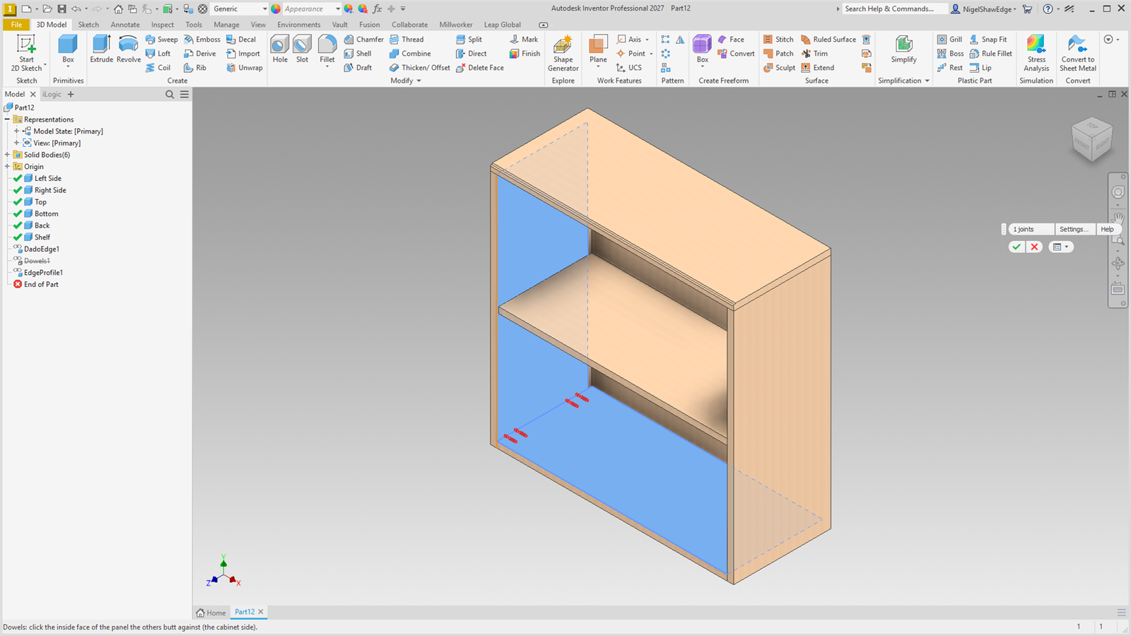
Dowels, Cam Dowels, Confirmat (and Hardware Hole nodes made before), Place Hole, Face Bore (nodes made before), Domino, Biscuit, Clamex P, Pocket Screws, LED Channel, Tongue, Groove, Shaker Door, Corner Quirk, Tongue & Groove, Dado Join, Dado Edge, Edge Inset, Miter Join, Stop Shoulder, CAM Corners, Lattice, Sunburst, Halving, Copy Body and Edge Profile open their tool again:
- The node is suppressed, so the part is as it was before it was made.
- Its picks are found again and lit, and its values come back (a value you changed since in Parameters shows as it is now), with the tool's own choices: fastener size, Rotate 90°, quirk style, Halving's direction, Edge Profile's profile and Flip, Copy Body's direction, edge or path, Rotate, Fill and number of copies.
- Change values, add picks or take picks back. The preview follows every change; Settings… changes (such as how many Confirmats per joint) show at once.
- OK makes it again with the picks as they are now, in its place in the browser with the same name, as one undo step. You can pick faces and bodies made after the node; the node then moves below them. Cancel puts it back as it was.
Tools that edit their parameters
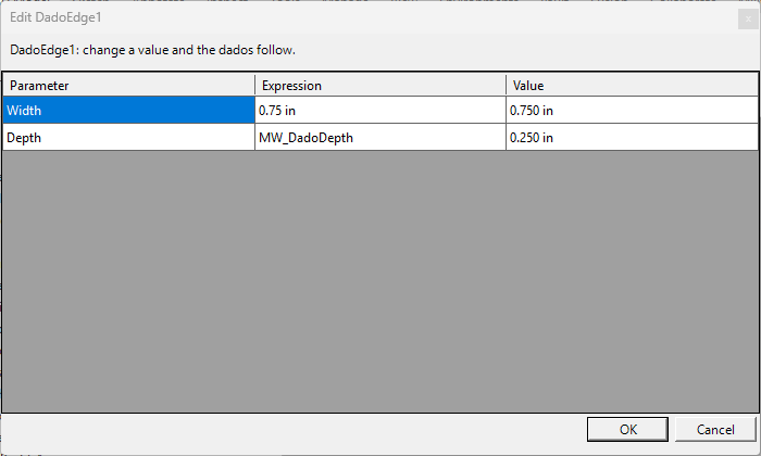
Panel Maker lists its own parameters to change, as do nodes made before their tool could open again (Copy Body, Halving and Edge Profile nodes made before this version: delete and make them again to get the full edit). Hinge Holes and Shelf Holes open their popup with the current sizes and an Update button.
Tool units
Show every tool size in inches or millimetres.
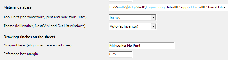
- Millworker Settings (Settings panel) → Tool units.
Choose Inches (the default) or Millimetres. Every tool's sizes are shown in that unit: the mini toolbar values, the Settings… grids (hinge, shelf, dowel, fastener and woodwork sizes) and the MW_ parameters the tools make.
- A size kept as a plain length in the other unit is shown converted and saved that way: 17 mm shows as 0.6693 in.
- Expressions and parameter names are left as typed:
MW_DadoDepth + 1/16stays as it is. - A length typed with a unit keeps it:
35mmor1.5in. With no unit, the tool unit is used.
Parameters and MW_ names
Every size a tool makes is a user parameter in the part's Millworker group, so changes follow through.
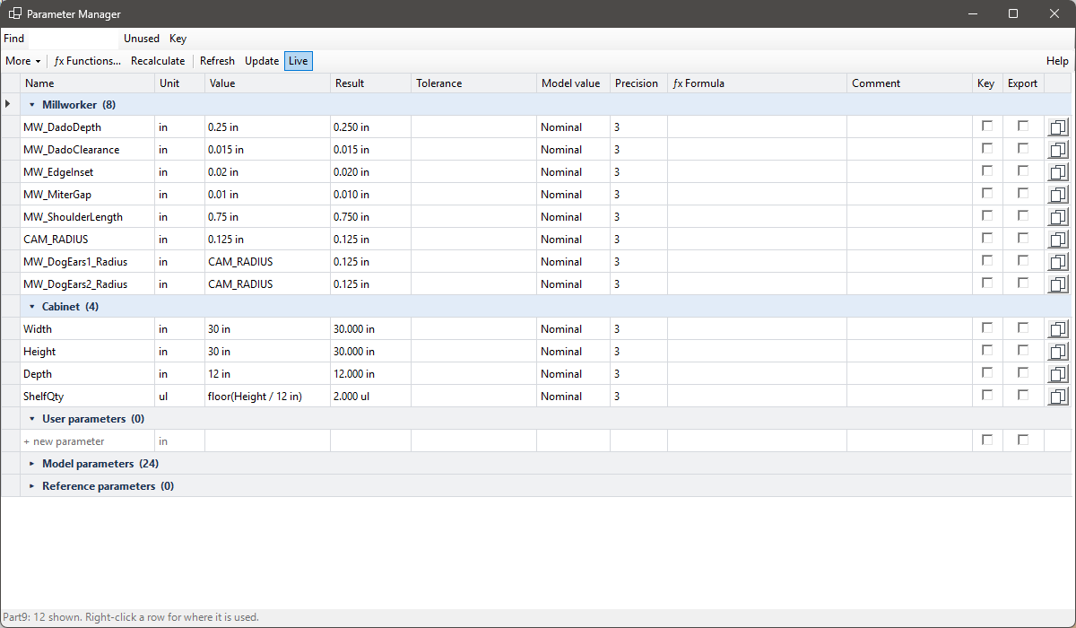
Millworker never types a fixed number into a feature. Every size, depth and distance a tool makes is a user parameter in the part's Millworker parameter group. Change the parameter and every feature that uses it updates.
Shared part parameters
The first time a tool runs in a part it adds these, set from Millworker Settings:
| Parameter | Default | Used by |
|---|---|---|
MW_DadoDepth | 1/4″ (0.25 in) | Dado Join, Dado Edge |
MW_EdgeInset | 0.02 in | Edge Inset |
MW_MiterGap | 0.01 in | Miter Join |
MW_DadoClearance | 0.02 in | Dado Join, Dado Edge, Halving, Groove, Shaker Door |
MW_ShoulderLength | 0.75 in | Stop Shoulder |
CAM_RADIUS | 0.125 in | CAM Corners, Stop Shoulder, Dado Join, Halving |
Each tool's own parameters
A value box with a parameter's name in it uses that parameter. Anything else typed becomes the tool's own parameter, named MW_Tool#_What: MW_DadoEdge1_Depth, MW_EdgeInset1_Inset, MW_PanelMaker1_Thickness, MW_Dowels2_Setback.
Only counts (dowel pairs, shelf hole rows, holes per row, middle hinges) and the 118° drill point are fixed when a feature is made.
Settings
Millworker Settings
Default sizes for the tools, tool units, and the shared material database folder.
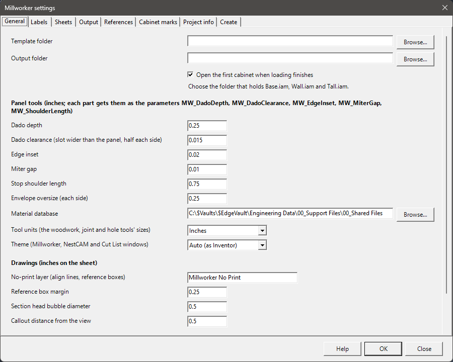
- Millworker tab → Settings panel → Millworker Settings. On every ribbon.
| Setting | Default | What it does |
|---|---|---|
| Dado depth | 0.25 in | Starts MW_DadoDepth in a part that has none. |
| Edge inset | 0.02 in | Starts MW_EdgeInset, used by Edge Inset. |
| Miter gap | 0.01 in | Starts MW_MiterGap, used by Miter Join. |
| Dado clearance | 0.02 in | Starts MW_DadoClearance: a slot is cut this much wider than the panel that fits in it, half on each wall, so the panel is not a press fit. 0 puts the walls right on the panel. |
| Stop shoulder length | 0.75 in | Starts MW_ShoulderLength, used by Stop Shoulder. |
| Envelope oversize | — | The oversize on each end and side a new Waste Envelope gets. |
| Tool units | Inches | See Tool units. |
| Theme | Auto (as Inventor) | The look of the Millworker, NestCAM and Cut List windows: Auto is light or dark as Inventor's theme is; Light or Dark sets it. The same colours as CabinetCAD's windows. A window takes a change the next time it opens. |
| No-print layer | Millworker No Print | The layer the drawing tools' align lines and reference boxes go on. Made in the drawing the first time (red, dashed) when it has none of that name, and always set not to plot. |
| Reference box margin | 0.25 in | How far a reference box stands out from its view, on the sheet. |
| Section head bubble diameter | 0.5 in | The size of a section line's head bubble on the sheet; its arrow and the tail are sized from it. |
| Callout distance from the view | 0.5 in | How far a drawing callout's boxed note sits out from the side of its view. |
| Material database | — | The folder that holds Millworker Materials.db. Put it on a shared drive so every PC uses the same materials, edgebands, edge profiles, functions and hardware library. |
| Textures folder | — | The folder of texture and finish pictures (a shared drive, say). The Material Manager keeps a picture from it by its path inside it, so after a move, set the new folder here and the pictures are found again. NestCAM and CabinetCAD use it too. |
| Template folder, Output folder | — | Used by CabinetCAD's cabinet templates (Base.iam, Wall.iam, Tall.iam). |
More tabs: Labels, the label each ViewCube view gets from Update Labels; Sheets, the drawing template and sheet layouts the Drawing Builder uses (drag the layouts into sheet order, tick the ones the builder makes, and set what each is Used for; the layout editor places views, a parts list and a revision table), the sheet index table style and the sheet name format; Output, the Drawing Output profiles; References, for Reference Tables: the projects root and workbook name, the template workbook new workbooks start from, a table style for each group, the optional groups (Panels, Metal, Glass, Purchased), I use Vault (only then do the messages say to get or check out the workbook in Vault), Use INNERGY (only then does Millworker look materials up in INNERGY, check them against it, and take thickness from micValue; unticked, it works from the Material Manager alone) and your INNERGY email and API key (kept on this computer, encrypted, shared with InvInnergy); Cabinet marks, the Cabinet Marker types; Project info, the iProperties Project Info fills in and pushes down; and Create, the projects root, how new project, work order and file names are made, and the template for each kind of file Create makes.
Changing a value in an open part
The settings seed parameters in a part that has none yet. When you click OK with a part open and its MW_DadoClearance differs, Millworker asks, names the old and new value and sets it in that part (one undo step); every slot follows. Other parts keep their own value until they are open and Settings is OK'd again.
The tools' own Settings… buttons (Dowels, Hinge Holes, Shelf Holes and the fasteners) hold their own sizes; those are covered on each tool's page.
Panel Marking
 Panel Marking
Mark edgebanding, grain and miters on panels for the cut list and the nest, and show or clear the marks.
- An assembly of panel parts (for example made with Make Components from a multi-body part).
- Millworker tab → Panel Marking panel.
Marks are kept in the part files (attributes on faces and edges), so every copy of a part carries them. The cut list, the BOM and NestCAM read them. Save the parts after marking.
Each marking command opens a mini toolbar. OK keeps the changes and Cancel puts back everything changed in that session. Esc or starting another command also keeps them.
Mark EdgeBand
- Choose the band in the toolbar (Bands… edits the list; with a material database it opens the Material Manager).
- Click edge faces. One click bands a face. A face with another band switches to this one; a face with the same band loses it.
- Panel select on the toolbar: click a panel and every edge round it is banded at once (not hole or groove walls); click it again to take them all off. Edge select goes back to single edge faces. The choice is kept for the Inventor session.
- Pick another band in the toolbar and carry on: a part can carry as many bands as needed.
With the material database, the band's woodgrain picture or colour goes on the face too.
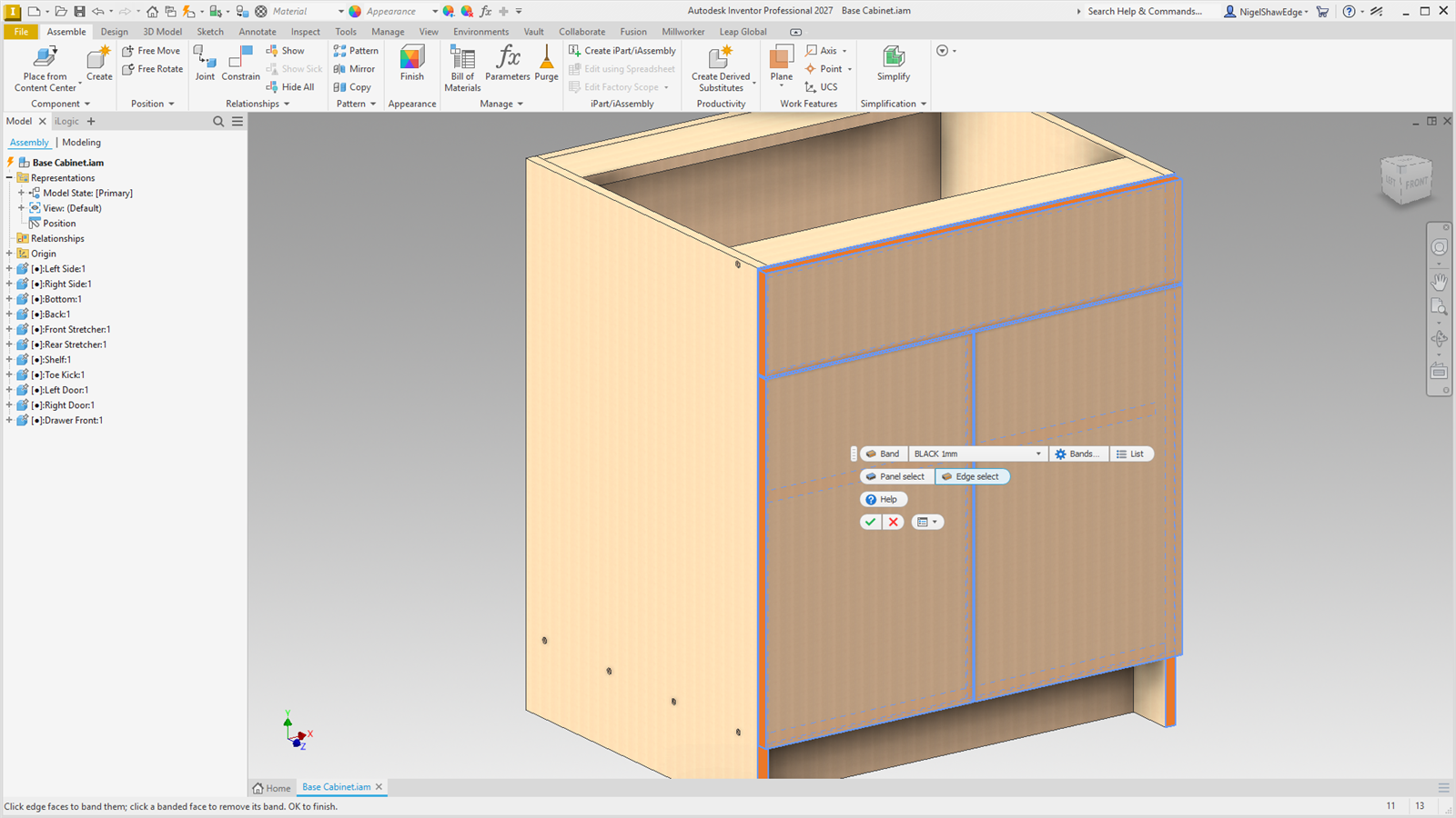
The Edgebands list opens beside the model with the tool (close it with its X; List on the toolbar brings it back). It has a row for each band on each part with how many faces carry it. Pick rows (Ctrl or Shift for several) to light their faces, then Remove band, or Switch to give them the band chosen beside it.
 Mark Grain
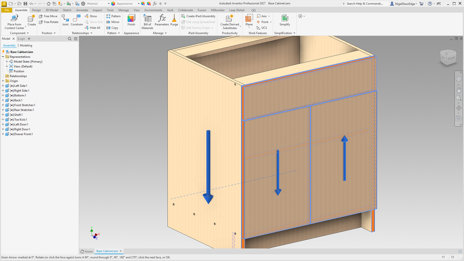
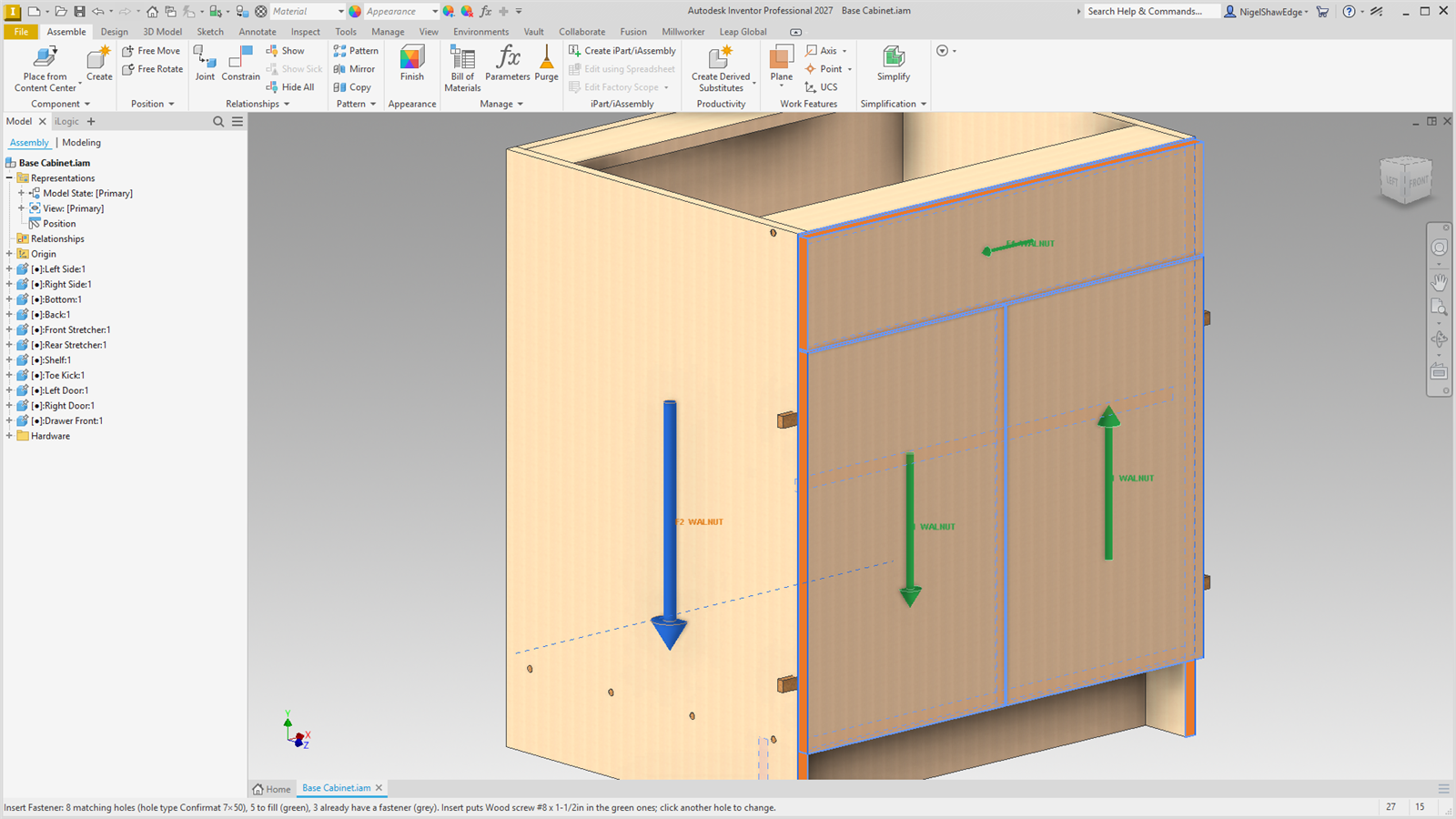
- Start Mark Grain. Panels already marked show a blue arrow; panels whose material has Grain ticked but no mark yet are highlighted amber.
- Click a panel's veneer face. A blue arrow shows the grain (along its longest straight edge to start) and marks it for the nest.
- Rotate 90°, or a second click on the face, turns it across.
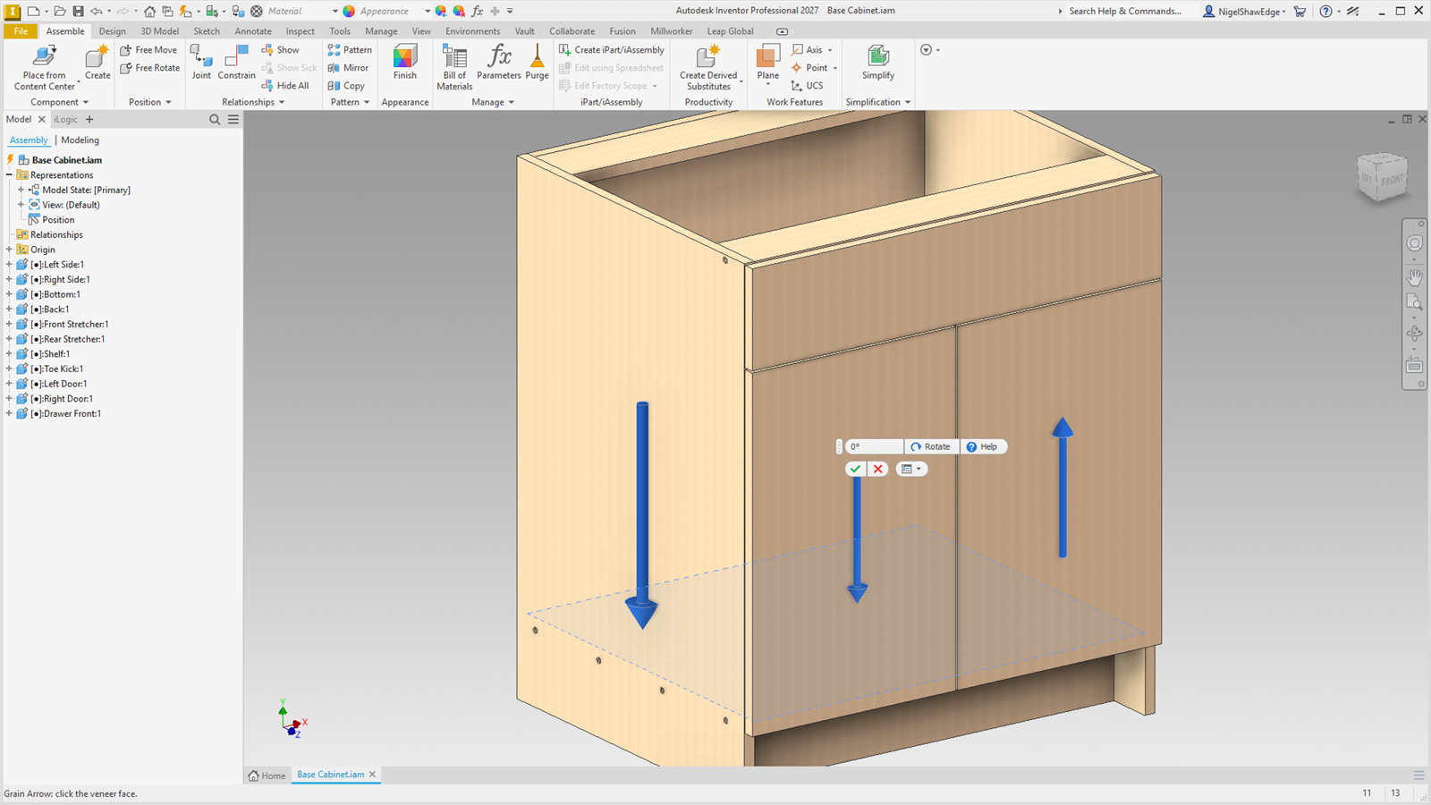
A panel has one grain; a new mark replaces the old one. Library and Content Center parts are left out.
 Mark Miter
Click mitred edge faces. The nest adds the miter allowance (1/4″ by default) on those edges, so there is material to machine the miter later. Miter Join marks its faces for you.
 Show Marks
Banded faces show orange, grain edges blue with an arrow along the grain on each veneer face, mitred faces purple, and veneers green (Face 1) or orange (Face 2). Click again to hide.
 Clear Marks
Click panels to remove all their marks.
 Cabinet Marker
Mark parts as Left door, Right door, Drawer front, Toe kick and the rest; each type lights up in its own colour.
- An assembly: Panel Marking panel → Cabinet Marker.
- When it starts, it marks the parts it can tell the type of by itself (only parts not marked yet), and the toolbar's Found line says what: doors from their hinge cups (cups on the left as seen from the door's front make a Left door; on the right, a Right door; at the top, a Lift-up door; at the bottom, a Drop-down door), drawer fronts (a panel facing the front with no hinge cups, nothing in front of it and the cabinet behind it), and toe kicks (the same, at the very bottom and no more than 200 mm high). Ctrl+Z takes all of these off in one step. A part whose mark you take off by hand isn't typed again.
- Every marked part lights up filled in its type's colour, so it shows in a busy model.
- Choose a type in the toolbar (Left door, Right door, Lift-up door, Drop-down door, Drawer front, Drawer box, False front, Toe kick, End panel, Shelf, Fixed panel, or your own).
- Click parts to mark them as that type. Click a part already marked as it to take the mark off; click one marked as another type to change it.
- OK (or Esc) finishes. Save the assembly to keep the marks.
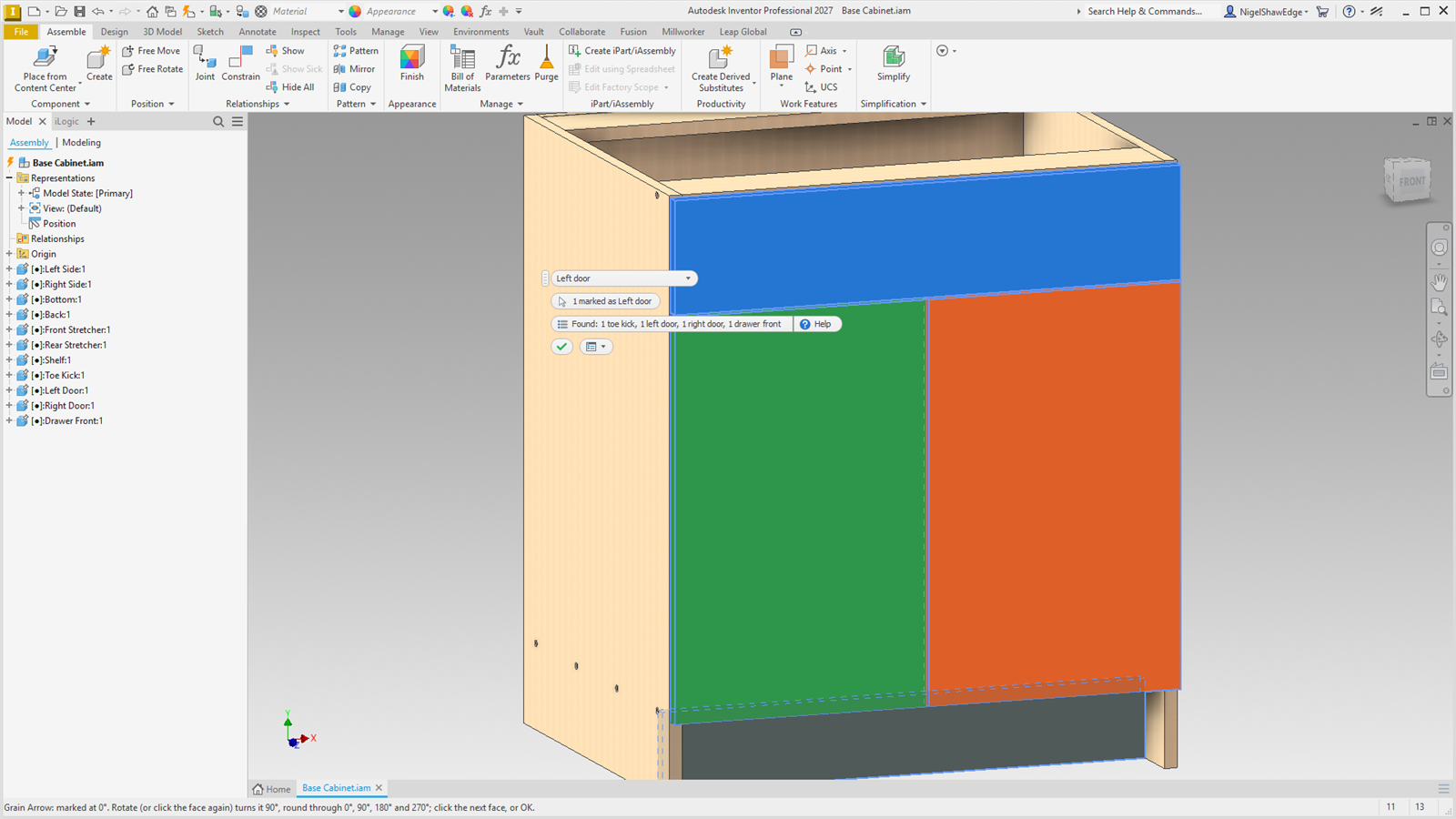
The mark is kept on the part's place in the assembly, not on the part file, so one door part can be a left door in one cabinet and a right door in another. A part inside a sub-assembly is marked in that sub-assembly (it must be writable), so the cabinet's marks go with it into every assembly and drawing it's used in.
Which way is the front: the assembly's Front view (as its ViewCube has it) decides left and right, so a cabinet modelled facing another way still comes out right. Check the found types the first time on a new kind of model: a drawer front is only a guess from where the panel sits, and a false front sits just like one.
Types and colours are in Millworker Settings, Cabinet marks tab: add, rename or remove types, double-click a colour to change it, and choose each type's opening lines for drawings (left, right, up, down or none). Show Mark Types draws them.
Joins
 Dado Join
Cut a dado in the master panel and run the panels into it, however they sit: overlapping, touching or short of it.
- A multi-body part: a master panel (a cabinet side, a top) and the panels going into it (bottom, shelves, sides) at right angles to it.
- They can sit any way: running into or through the master (as Panel Maker leaves them at a corner, both filling the corner), their end on the master's face, or short of it with a gap. Nothing needs doing to them first.
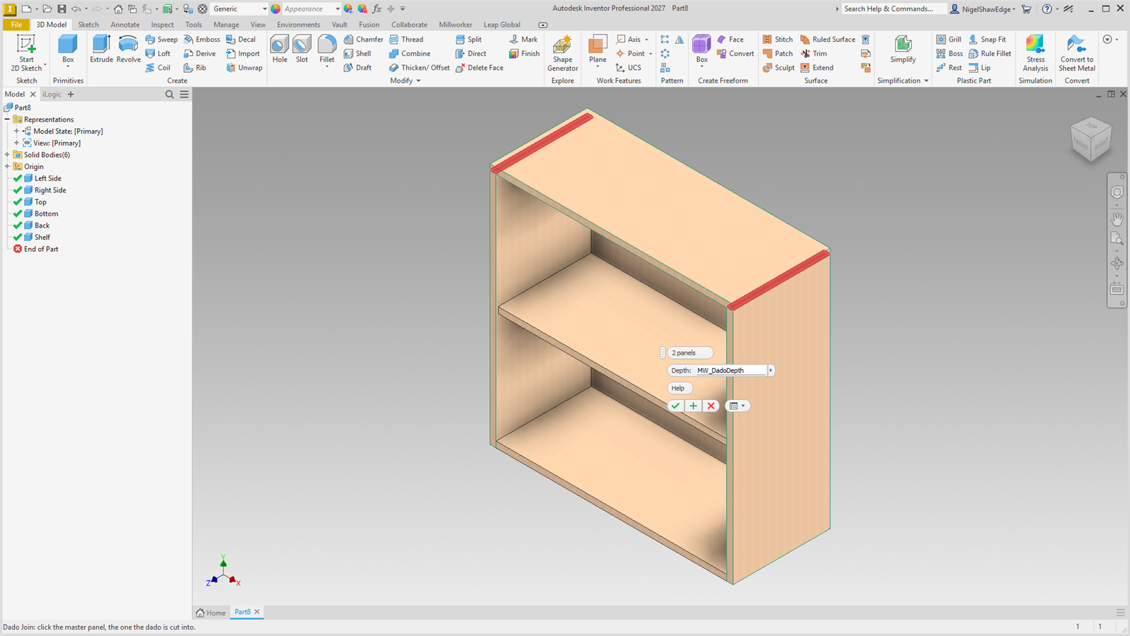
- Click Dado Join (Joins panel).
- Click the master panel: the one the dado is cut into.
- Click the panels going into it, as many as you like (click one again to take it back).
- Check the Depth (starts as
MW_DadoDepth, 1/4″). The dados preview in red, and anything cut off a panel that ran too far in shows in orange. - Apply to carry on, or OK to finish.
What it makes
- Each panel is made to end the depth into the master: trimmed there where it runs further in (a hidden work plane the depth into the master's face), and thickened on first where it falls short.
- The master is cut by the panel: the dado (a rabbet when the panel sits at the master's edge).
- Clearance: the dado's two walls are each cut back
MW_DadoClearance / 2, so the slot is wider than the panel. The tongue stays the panel's own thickness. - CAM Corners: a dado that stops inside the panel gets dog ears in its square inside corners, the cutter's radius (
CAM_RADIUS, 1/8″), as a CAM Corners node of its own. A dado that runs out at both edges gets none. - One node per panel; double-click it to change the depth.
 Miter Join
Miter two panels at their corner, with a gap, and mark the miters for the nest.
- A part with two panels meeting at a corner, butted or overlapping (a waterfall end and a top, for example).
- Click Miter Join (Joins panel).
- Click panel 1, then panel 2. The parts cut off preview in red.
- Check the Gap (starts as
MW_MiterGap, 0.01″). - Click the next body to make this miter and start the next, or OK.
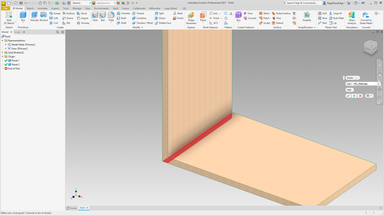
- The miter plane runs through where the outside faces meet and where the inside faces meet (hidden construction geometry).
- Each panel is trimmed half the gap short of it.
- A panel that butts against the other's inside face is first extended to its outside face.
- The mitred faces are marked as miters for the nest (see Mark Miter).
Parameters: MW_MiterPanels#_Gap and _Extension.
 Halving
Halve two crossing bodies into each other, with clearance and CAM corners, and keep it parametric.
- Two bodies that cross, such as an egg-crate divider or two lapped boards, running with the part's axes.
- Click Halving.
- Click the first body (it loses the part above the mid plane), then the second (it loses the part below). The cuts preview in red.
- Turn steps the cut through the other directions if the first is not the one you want.
- Leave CAM corners ticked to clear the inside corners for the CNC cutter (orange in the preview).
- Apply or OK.
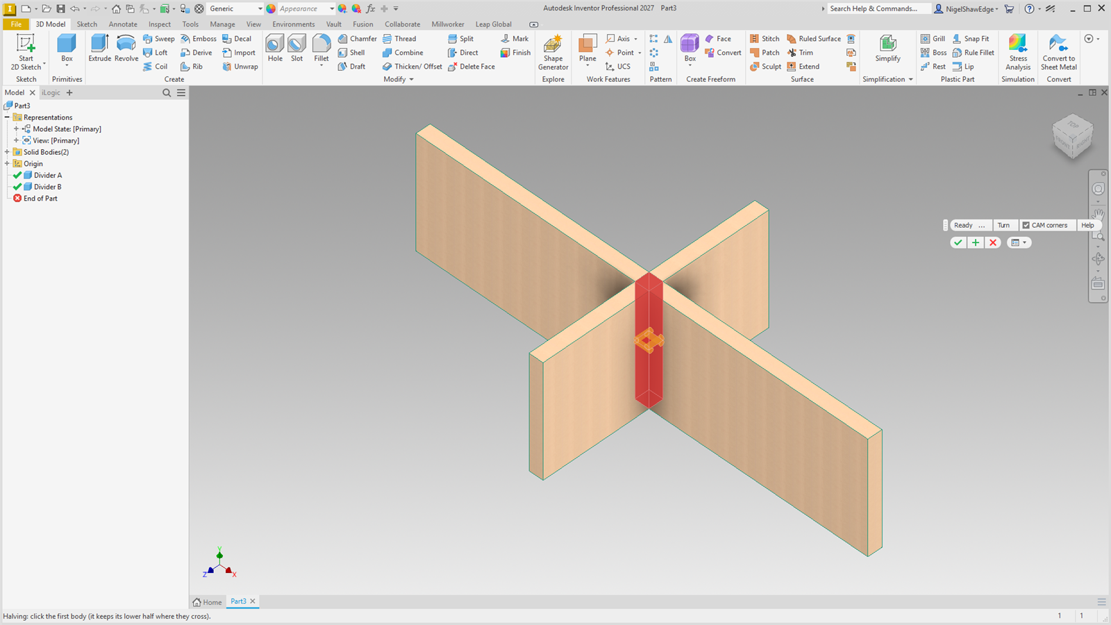
The mid plane first goes the way both bodies run right through the crossing, so neither is left with a groove. Each side of the slot sits MW_DadoClearance / 2 out from the other body's face. The halving follows when either body is resized or moved.
 Corner Quirk
Turn a butt corner into a dado or locking quirk joint, with a 1/8 or 1/4 in quirk.
- A corner of two panels: an upright V standing on a horizontal H, its end on H's face and its outer face flush with H's end.
- Click Corner Quirk (Joins panel).
- Click V's outer face (the outside of the corner), then the face of H that V stands on.
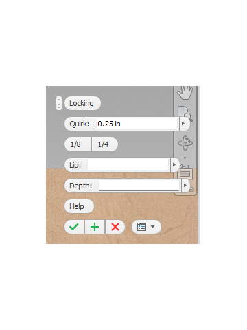
- Choose Dado or Locking (remembered for next time).
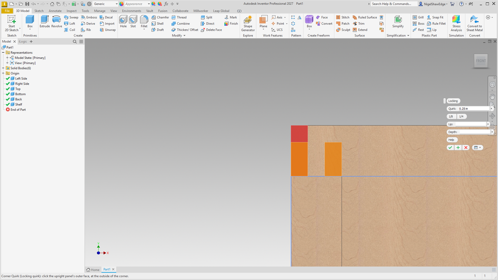
- Set Quirk, the step left at the outside corner; 1/8 and 1/4 buttons fill it in (1/4″ for 3/4″ panels).
- OK. The preview shows what H loses in red and what V gains in orange.
| Style | What it makes |
|---|---|
| Dado quirk | V runs down into a rabbet across H's end, leaving H a lip Lip thick (empty: a third of H's thickness). V overhangs H's end by the quirk. |
| Locking quirk | Across V's thickness, V's outer lip (the quirk wide), H's end tongue and V's inner tongue share the rest equally. V's lip and inner tongue run Depth into H (empty: H's thickness less the quirk). On 3/4″ panels with a 1/4″ quirk that gives three equal thirds and a 1/4″ × 1/4″ quirk. |
Parameters: MW_CornerQuirk#_VThickness, _HThickness, _Quirk, and _Lip or _Depth.
 Tongue
Put a centred tongue along board edges, with corners that meet cleanly.
- A part with boards to join edge to edge (a face frame, a glued-up top, a frame and panel).
- Click Tongue (Joins panel).
- Click the boards' edge faces, as many as you like.
- Set the tongue Width (its thickness, centred on the board) and Length (how far it stands out).
- Apply or OK.
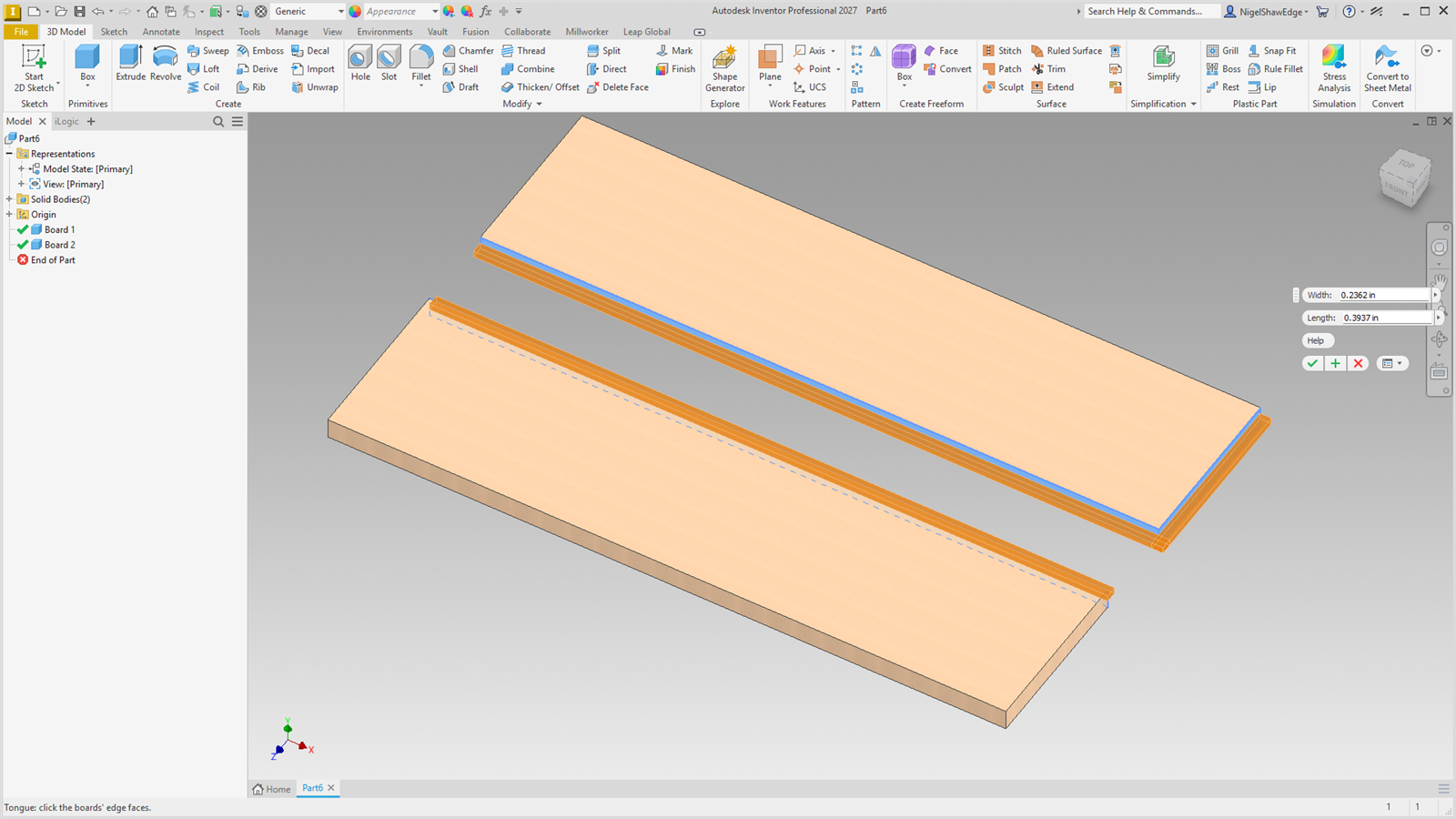
Where the face at a tongue's end has a tongue too (picked with it, or made before), the tongue runs on past the end by its length, so an outside corner is filled rather than left as a notch. Use Groove on the mating boards.
 Groove
Cut a centred groove along board edges, run out at both ends, sized for the mating tongue plus clearance.
- A part with boards that take a tongue or a panel along an edge.
- Click Groove (Joins panel).
- Click edge faces, as many as you like.
- Set Width and Depth. The groove is cut Width plus the dado clearance wide, centred.
- Apply or OK.
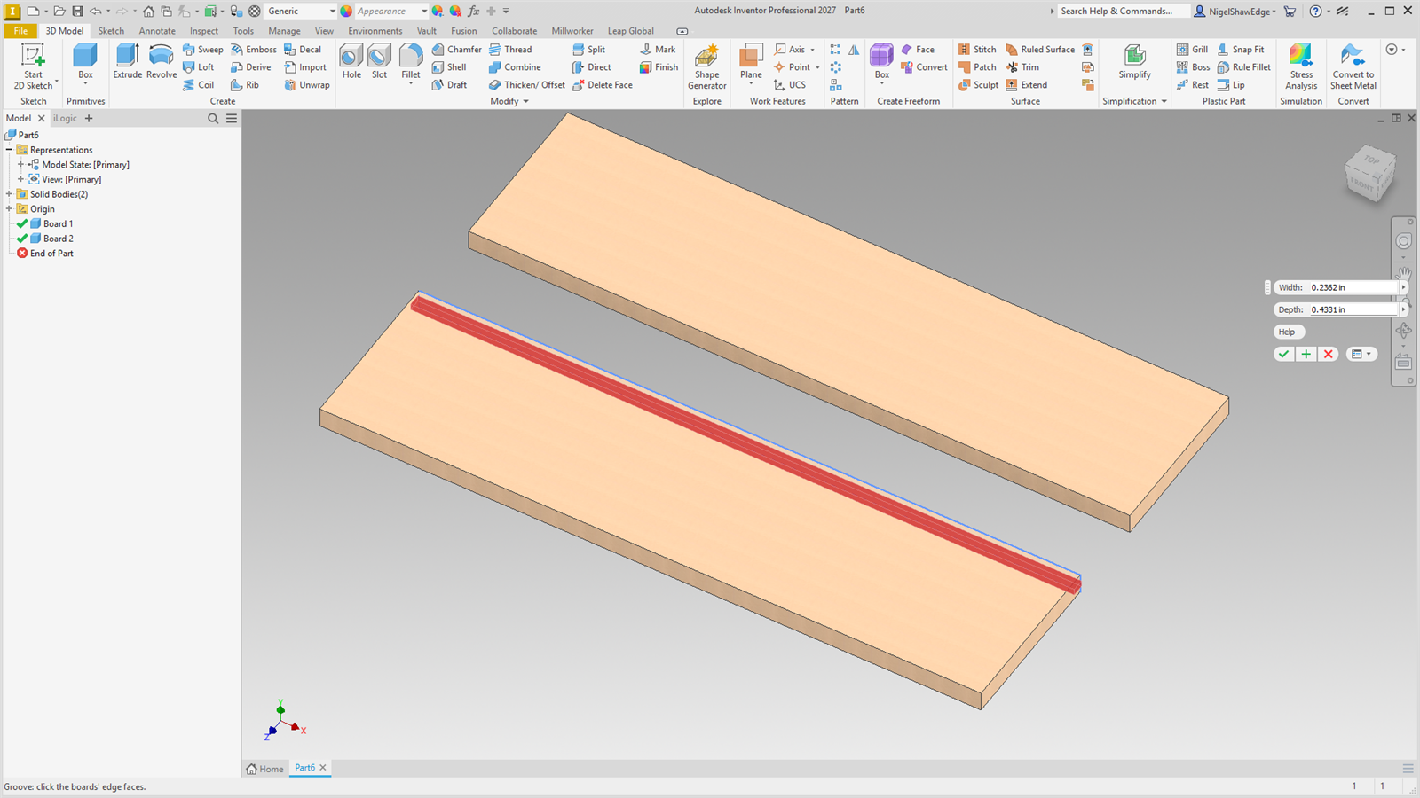
The groove runs out at both ends through all of the board, a tongue on its end included. Its sketches sit hidden inside the node, so the browser stays tidy. Nodes made with the earlier paired Tongue & Groove tool still edit as before.
Fasteners
 Dowels
Drill System 32 dowel pairs in butt joints, laid out from the cabinet side's front edge.
- A multi-body cabinet: a side and the panels that butt against it (bottom, top, fixed shelves).
Picks
- Click Dowels (Fasteners panel).
- Click the inside face of the panel the others butt against (the cabinet side).
- Click its front edge: the reference the layout is measured from.
- Click the inside face of each butting panel. Click one again to take it back. Every joint previews.
- Apply drills them and carries on with a new side; OK drills and finishes.
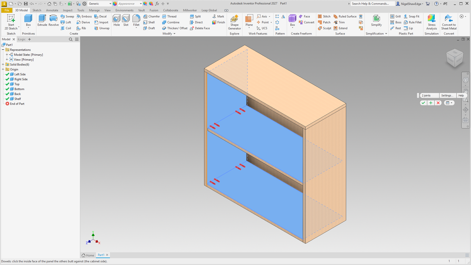
Layout
- Holes go in pairs, 32 mm apart.
- The first hole is 37 mm from the side's front edge, whatever the butting panel's own setback. The last pair is 37 mm from the joint's back end.
- More pairs sit between on the 32 mm grid when the joint is longer than Most between pairs (256 mm).
- Across each joint, every centre is 9 mm in from the butting panel's inside face.
- Dowels: 8 mm, 12 mm into the face and 25 mm into the edge.
Settings…
Settings… in the mini toolbar sets the starting values. Pairs per joint:
| 0 | As many as fit under Most between pairs. |
| 1 | One pair in the middle. |
| 2 or more | One pair the first-hole distance from each end, the rest spread evenly between on the 32 mm grid. The spread is a round(…) of the joint's length, so pairs re-spread when a panel changes size. |
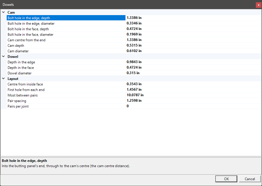
Every size is a parameter MW_Dowels#_… (Setback, Pitch, FromInside, each hole's diameter and depth), and each hole's sketch is dimensioned to the joint, so the holes move with the panels. Each hole is tagged for Place Hardware (a dowel, 8x35).
 Cam Dowels
Bore cam fittings and their dowels in pairs on the System 32 layout.
- As for Dowels: a side and the panels butting against it, for knock-down (RTA) assembly.
The picks and layout are the same as Dowels: the side's inside face, its front edge, then each butting panel's inside face. Each pair is a cam fitting and a dowel.
| Hole | Size | Where |
|---|---|---|
| Cam housing | 15.5 mm × 13.5 mm deep | In the butting panel's inside face, 34 mm in from its end. |
| Rod | 8 mm × 34 mm | In the butting panel's edge. |
| Thread end | 5 mm × 12 mm | In the side's face. |
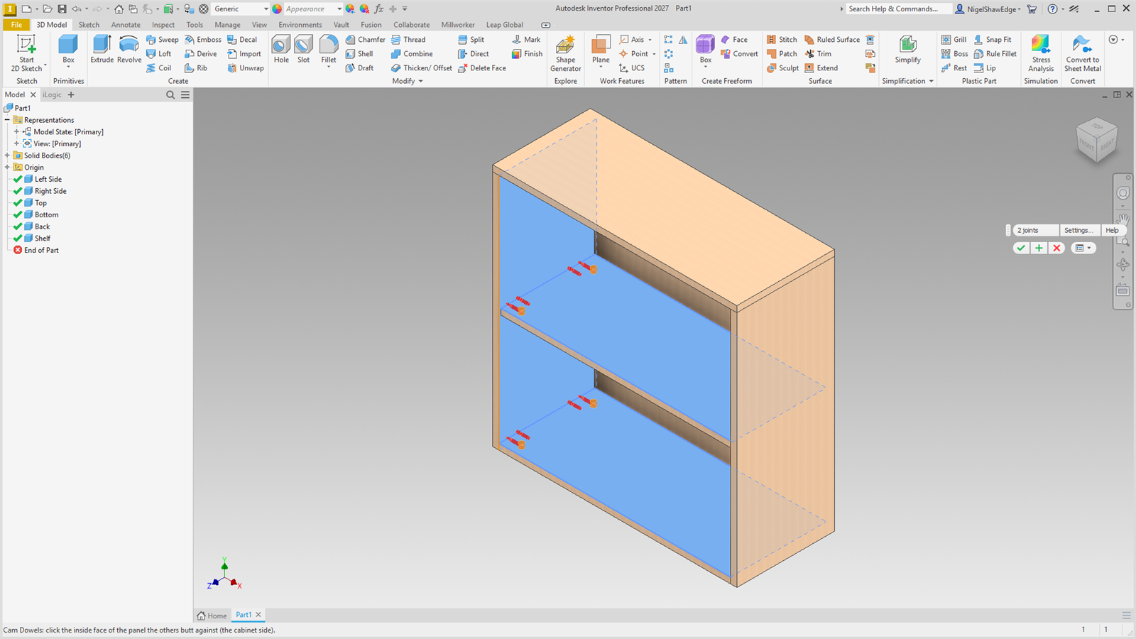
Settings… holds the shop's cam setup and the pairs per joint. Parameters are MW_CamDowels#_…, including CamFromEnd. Each housing, bolt hole and dowel is tagged for Place Hardware.
 Confirmat
 (joint screw) holes in a butt joint, from a hole type with an edge pilot: through the side with its head, a pilot into the butting panel's end.
- Click Confirmat (Fasteners panel).
- Choose the hole type in the mini toolbar's list. Only hole types with an edge pilot are listed. The last one chosen comes up next time.
- Pick the side's inside face, its front edge, then each butting panel's face.
- Apply or OK.
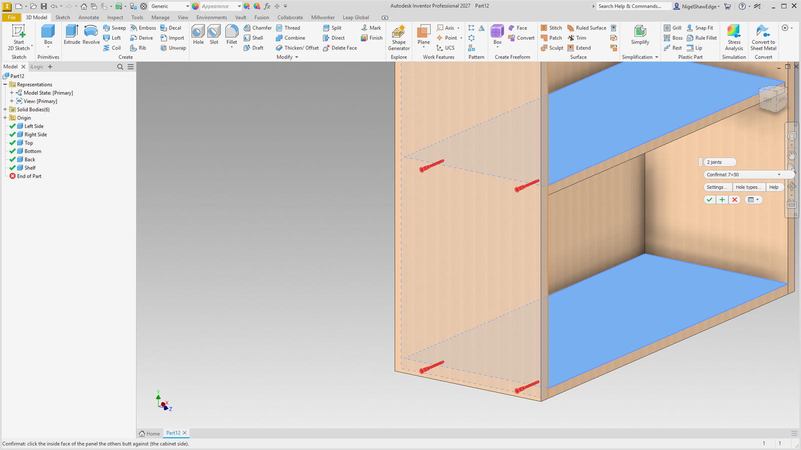
- The hole goes through the side, drilled from its outside face, with the hole type's head (countersink, counterbore or none).
- The pilot goes into the butting panel's end: the hole type's edge pilot Ø and depth.
- Every size is a parameter (MW_Confirmat1_…) in the Millworker group: change one and the holes follow.
- The holes are tagged with the hole type and its fastener, so Insert Fastener and Place Hardware put that part in.
Fastener layout (all one-at-a-time fasteners)
Confirmat, Domino, Biscuit, Clamex P and Pocket Screws place one fastener at a time, each tool with its own layout in Settings…:
| First from each end | 50 mm (about 2″): the first and last fastener. |
| Most between | 300 mm (about 11-13/16″): more are spaced evenly between, no farther apart than this. |
| How many per joint | An exact count; 0 lets the joint's length decide. |
| Centre from inside face | 9 mm. |
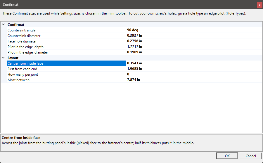
With a hole type chosen, its Settings… is the layout only. The Confirmat sizes there are used with Settings sizes; those holes are tagged by size for Place Hardware (7x50, the longest of 30–70 mm that fits).
 Place Hole
Holes of a hole type in a panel, on a sketch's points or measured from two edges, previewed as they will be cut.
- A part with the panel as a body.
- For On sketch points: a sketch with a point where each hole goes.
- Click Place Hole (Fasteners panel).
- Choose the hole type in the mini toolbar's list (each with its category's icon). Edit holes… opens Hole Types to make or change one; the list is read again when it closes.
- Choose how the holes are placed: On sketch points or From edges.
- Pick (below). The holes are previewed as they will be cut: the head, the hole, its depth and drill point.
- Apply or OK.
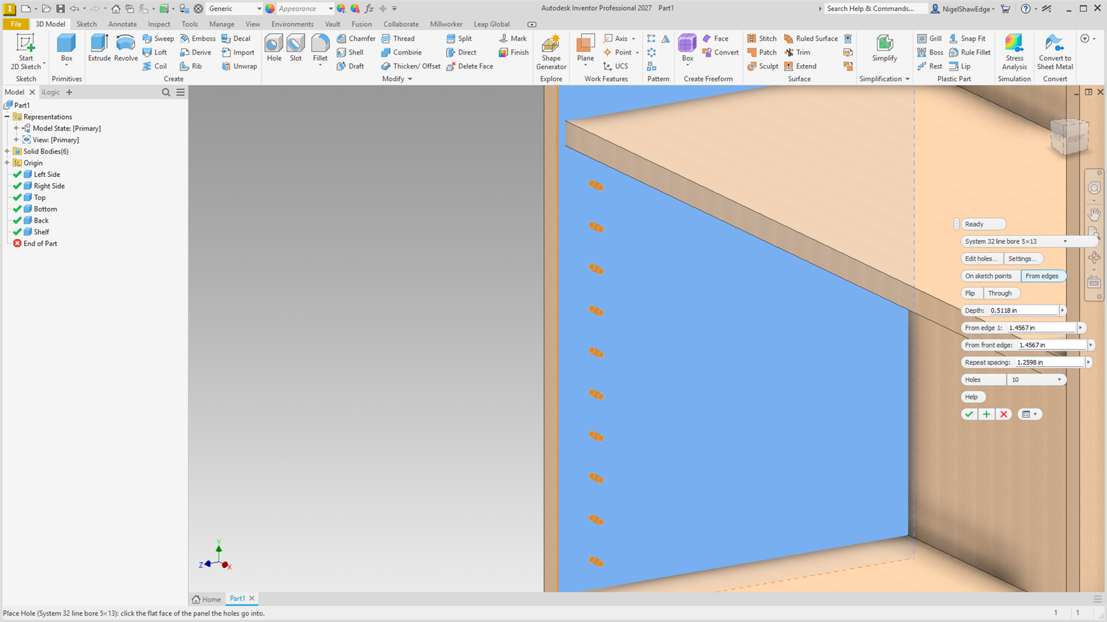
On sketch points
Pick a sketch: a hole goes on each of its own points (projected points and circle centres are left out). Or pick its points one by one. The holes follow the sketch when it changes. When the holes are made, the sketch is turned off (it is still there and still drives the holes; Visibility in the browser shows it again).
From edges
Pick the flat face the holes go into, then the edge (or edges) they are measured from. Holes is how many. How the row is spaced follows the hole type's category:
| Confirmats and wood screws | Pick the face and one edge. The first and last holes are From the ends in from each end of that edge (50 mm to start), and the holes between are spread evenly; one hole goes in the middle. On a panel's face (a back screwed into the bottom's edge, say) pick the face and the edge line: the holes are From the line up from it (9 mm to start, half an 18 mm panel), a dimension you can change. On a panel's edge (a narrow face), Centre (on to start) puts the holes in the middle of its thickness instead; turn it off to use From the line there too. The edge's length is a parameter (MW_PlaceHole1_EdgeLength), so when the panel gets longer or shorter the holes spread out again. |
| Dowels | Pick the face, the edge the row runs along, then the front edge. The first dowel is From front edge back from it and From edge 1 across; the rest follow back from the front, Dowel spacing apart, in the dowel machine's 32 mm steps (32, 64, 96, 128…). |
| Shelf holes and the rest | As dowels, from the front edge, with Repeat spacing typed (32 mm to start: System 32). |
A row that is too long for the panel just stops at the last hole that fits: the rest are left out and the status bar says how many. Settings… sets the distances a new placement starts with.
The hole
| Flip | Drill from the other side: from edges, from the panel's opposite face (the head goes there); on sketch points, the other way from the sketch. |
| Through | Through the panel, else blind to the depth. Starts as the hole type is. |
| Depth | How deep a blind hole goes. Starts as the hole type's depth; change it for these holes only. |
Every size and distance is a parameter (MW_PlaceHole1_…) in the Millworker group. Each hole is tagged with its hole type and the hole type's fastener, so Insert Fastener and Place Hardware find it. Double-click the node to open the tool again.
 Hole Types
Your own list of holes: their sizes in mm, a cross-section of each, and the fastener that goes in it.
- Fasteners or Hardware panel → Hole Types (also with nothing open).
- Edit holes… in Place Hole, Hole types… in Confirmat and the Hardware Library.
A hole type is a named hole: Place Hole and Confirmat cut it. A set to start with is there the first time (Confirmat 7×50, dowels, shelf pins, a line bore, a hinge cup, Minifix, a countersunk screw, inserts, a through bolt); change or delete them as you like.
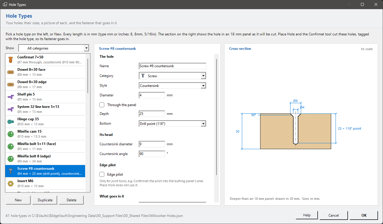
The list
Each row has its category's icon. Show filters by category. New, Duplicate and Delete are under it. Holes already cut keep their size when a hole type is deleted.
The fields
Every length is in mm, shown beside each box. Type mm or inches: 8, 8mm, 5/16in.
| Name, Category | What the tools list, and its icon. |
| Style | Plain (drilled), Counterbore (a wider step at the face, for a bolt's head) or Countersink (a cone at the face, for a screw's head). |
| Diameter | The hole's diameter. |
| Through the panel | Ticked: through. Else blind, to the Depth (from the face to the end of the full diameter), with a Flat or Drill point (118°) bottom. |
| Its head | Counterbore diameter and depth, or countersink diameter and angle (90° for most wood screws). |
| Edge pilot | Only for joint tools such as Confirmat: the pilot's diameter and depth into the butting panel's end. Place Hole does not use it. |
The cross-section
The selected hole drawn to scale in a panel (18 mm), with its sizes. It changes as you type, so you can see the hole before you cut it.
What goes in it
| Fastener | The part from the Hardware Library that goes in this hole, or (none). Place Hardware puts it in every hole of this type. Insert Fastener can set it for you (Remember for this hole type). |
| Needs a fastener | Ticked: the hole normally gets a part (a screw, dowel, cam, hinge). Unticked: left empty (shelf pins fitted later, a line bore). An empty hole type with no fastener gets nothing from Place Hardware. |
OK saves. A hole type that is not ready (a countersink narrower than the hole, a blind hole with no depth) says why. The list is kept in Millworker Holes.json beside the hardware library.
 Domino
 mortises in the side's face and the butting panel's end, for the tenon size you choose.
- A side and butting panels, as for Dowels.
- Click Domino and choose the tenon size in the toolbar: 4x20, 5x30, 6x40, 8x40, 8x50 or 10x50.
- Pick the side's inside face, its front edge, then each butting panel's face.
- Apply or OK.
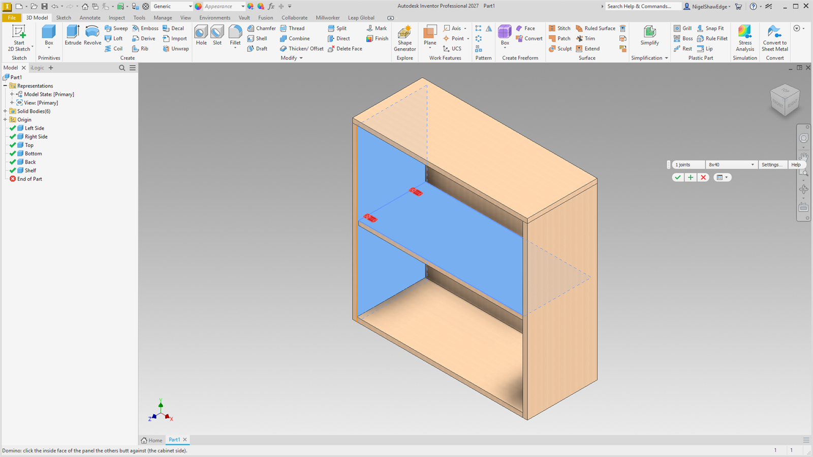
Each mortise is as long as the tenon is wide (the tight setting) with rounded ends. In the face it is 10 to 15 mm deep, so an 18 mm (3/4″) side is not gone through; the rest of the tenon plus 1 mm goes into the end. For 8x40: 12 mm in the face, 29 mm in the end. Layout as for Confirmat.
 Biscuit
#0, #10 or #20 biscuit slots cut as a 100 mm blade cuts them.
- A side and butting panels, as for Dowels.
- Click Biscuit and choose #0, #10 or #20.
- Pick the side's inside face, its front edge, then each butting panel's face.
- Apply or OK.
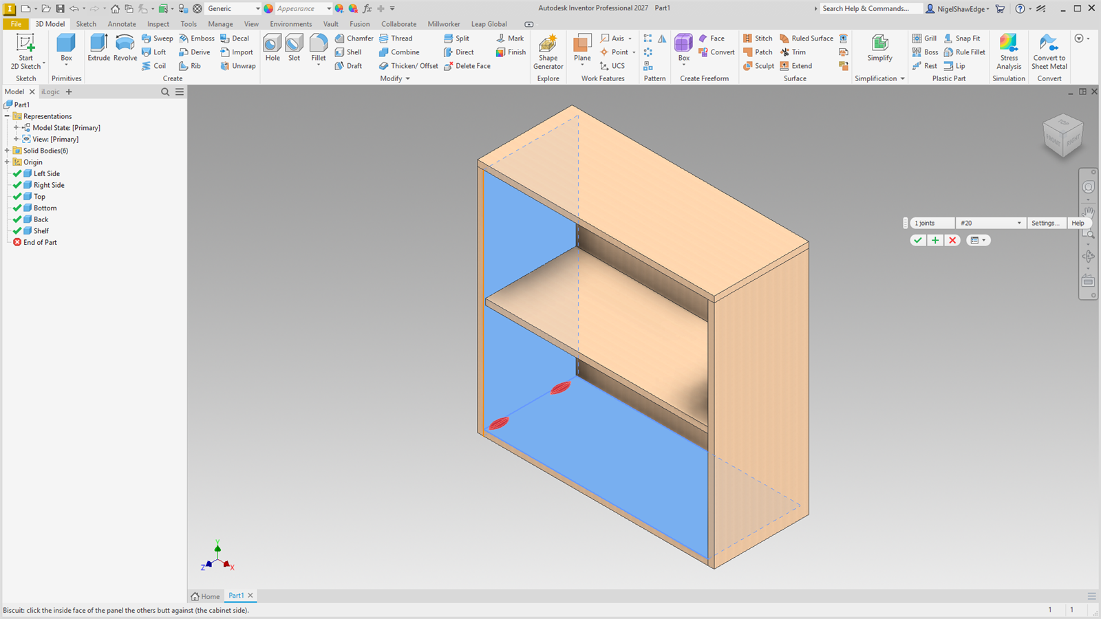
Slots are 4 mm wide, the segment of a 100 mm disc into each panel: longest at the face, with a curved bottom, half the biscuit's width plus 1 mm deep (66 mm long at the face for #20). Layout as for Confirmat.
 Clamex P
 connector slots in the side's face and the butting panel's end.
- A side and butting panels, as for Dowels.
- Click Clamex P and choose P-10, P-14 or P-18.
- Pick the side's inside face, its front edge, then each butting panel's face.
- Apply or OK.
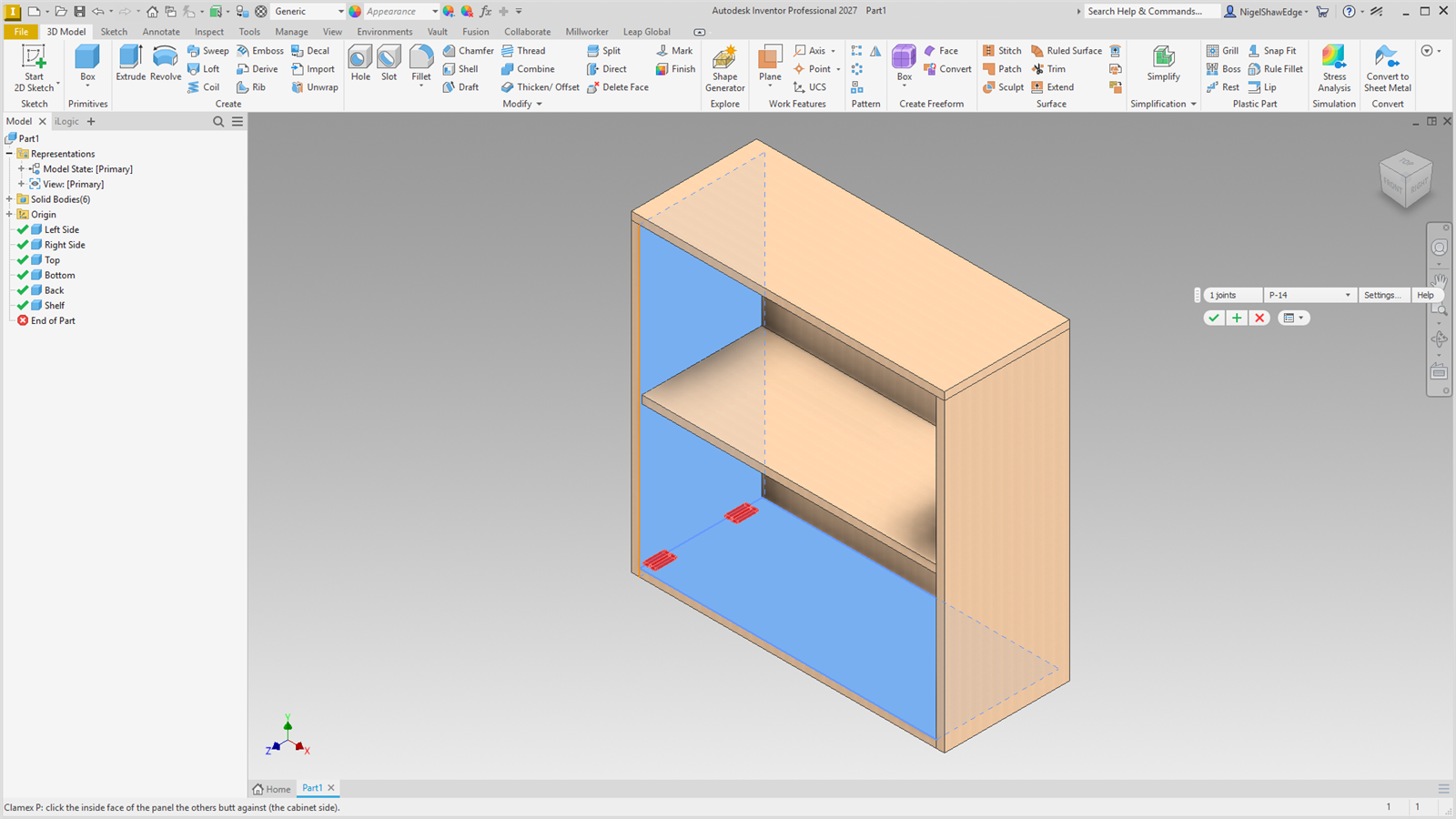
Each slot is straight with rounded ends, 7 mm wide (the P ribs are not modelled).
 Pocket Screws
Angled pocket holes in the butting panel, coming out of its end into the side.
- A side and butting panels (a face frame, a stretcher, a back rail).
- Click Pocket Screws.
- Pick the side's inside face and its front edge.
- Pick the face of each butting panel the pockets go in, usually its hidden face.
- Apply or OK.
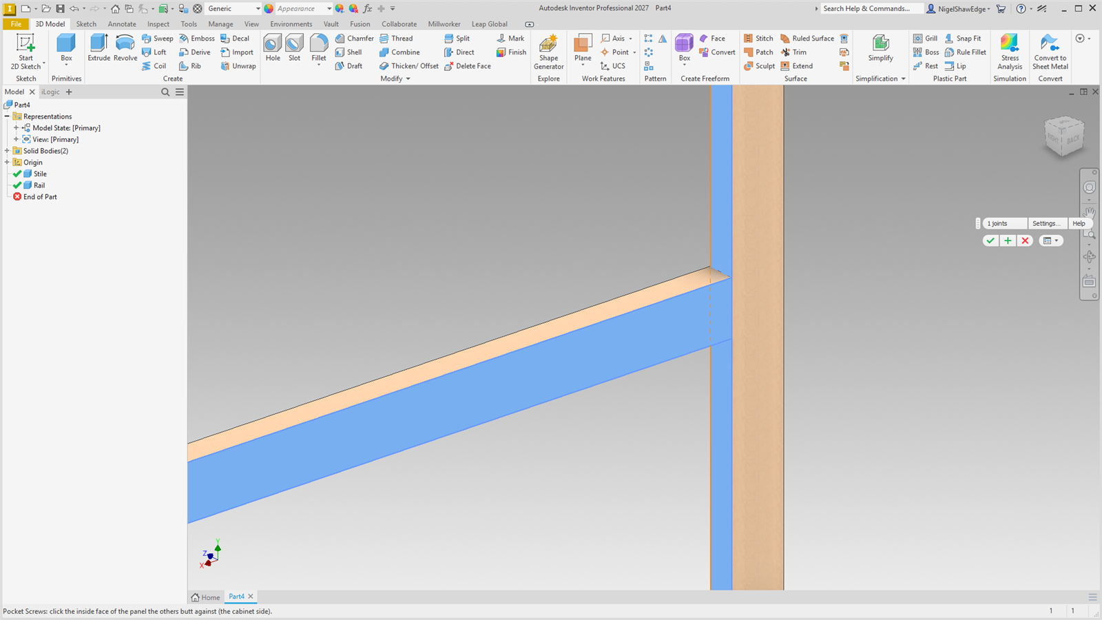
Each pocket is angled 15° to the face and comes out of the panel's end at Centre from inside face. It is a 9.5 mm (3/8″) pocket stepping to a 4 mm pilot 12 mm before the end. The pockets sit on a hidden work plane, so changing the angle or distances moves them. Layout as for Confirmat.
 Dog Bone
Dog bone pockets for countertop and subtop clamps, across a joint, spread from front to back.
- A subtop or countertop joint: two panels butting, or one panel with a sketch line drawn on its face where the joint goes.
- Click Dog Bone (Fasteners panel).
- Click the joint's centre line: the edge where the two panels meet, or a sketch line on the face.
- Click the front edge, then the back edge (both across the centre line).
- Check the sizes, and Flip to cut them from the opposite face (the underside) instead of the face the line is on (remembered for next time).
- Apply or OK. The preview shows the dog bones in red.
Each dog bone is two holes, one each side of the centre line, joined by a slot for the clamp's bolt, cut through every panel under it.
| Value | What it is |
|---|---|
| Hole diameter | Each hole (35 mm to start, for a Häfele-style clamp). |
| Centres distance | Hole centre to hole centre, across the joint (100 mm). |
| Slot width | The slot between the holes (12 mm). |
| Depth | How deep they are cut (18 mm). |
| From ends distance | The first and last dog bone, in from the front and back edges (3″). |
| Max gap | More are spread evenly between so none are further apart than this (24″). With no room for two, one goes in the middle. |
Every size is a parameter (MW_DogBone1_Hole, _Centres, _Slot, _Depth, _FromEnd), and the dog bones are spread over the measured front-to-back length, so they follow the panel when it changes. How many there are is set when they are made: make them again for more or fewer. Double-click the DogBone node to change its parameters. The values you use are the starting values next time.
Features
 Bubble Base
Make a bubble base to drive your base model. Create your panels on the bubble for easy model control.
- A part with a block body you made first (a sketch and an extrude), sized to the piece: the bubble.
- Features panel → Bubble Base.
- Click the block body. It turns clear (a see-through light blue look, Millworker Bubble), is renamed @BUBBLE (a second one @BUBBLE 2) and is marked as a bubble.
- Click it again to take the mark off: its own look and name come back.
- OK or Esc finishes.
Then make your panels on the bubble's faces with Panel Maker (they start into the faces). Change the bubble's sketch or extrude sizes and the model follows. The mark (attribute set Millworker.Bubble on the body) lets later tools find the bubble.
 Panel Maker
Click faces and make each one a separate panel body of a set thickness.
- A part with a block or surface shape whose faces are where the panels go (the outline of a cabinet, a box, a niche).
- Click Panel Maker (Features panel).
- Click faces, as many as you like; click one again to take it back. Each previews as a see-through blue panel.
- Set the Thickness. Panels always start into the face, the negative way (Flip shown pressed); press Flip to make them out from it.
- Apply to carry on with new faces, or OK.
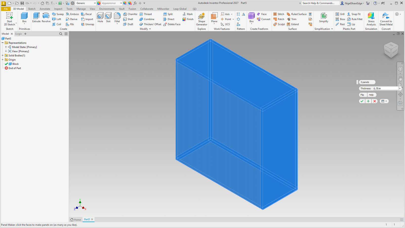
Every face becomes its own panel body (a thicken as a new solid), named Panel 1, Panel 2…, all in one undo step and one PanelMaker node. A shaped face previews as its bounding rectangle. A curved face (the side of a cylinder, a curved bubble) makes a curved panel the same thickness all round; it previews as the face itself. Flatten it with Make Flat. Parameter: MW_PanelMaker#_Thickness.
 Dado Edge
A rabbet (edge dado) along panel edges, Width in from the edge and Depth into the face.
- A part with panels that need a rabbet along an edge, for example the back edges of cabinet sides for a 1/4″ back.
- Click Dado Edge (Features panel).
- Click panel edges, as many as you like. Each previews in red.
- Set Width (in from the edge) and Depth (into the face). The face is the larger face along the edge; Swap cuts into the other one.
- Apply, or click the next body to make this one and carry on, or OK.
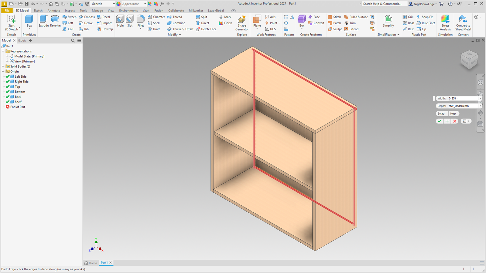
The rabbet's width is MW_PanelDado#_Width + MW_DadoClearance / 2 (a rabbet has one wall). Edges picked together make one DadoEdge node, all driven by the same width and depth; to give one edge its own size, make it in a selection of its own. The sketch is dimensioned from the projected edge, so the rabbet follows the panel.
 Stop Shoulder
Stop a dado short of the panel end, and notch the part running in it to suit.
- A part with a through dado (from Dado Join, say) that should stop short of the front edge so it does not show.
- Click Stop Shoulder.
- Click a face of the dado (its floor or a side).
- Click the panel's end face the dado runs out at.
- Set Shoulder (starts as
MW_ShoulderLength, 3/4″). - Apply or OK.
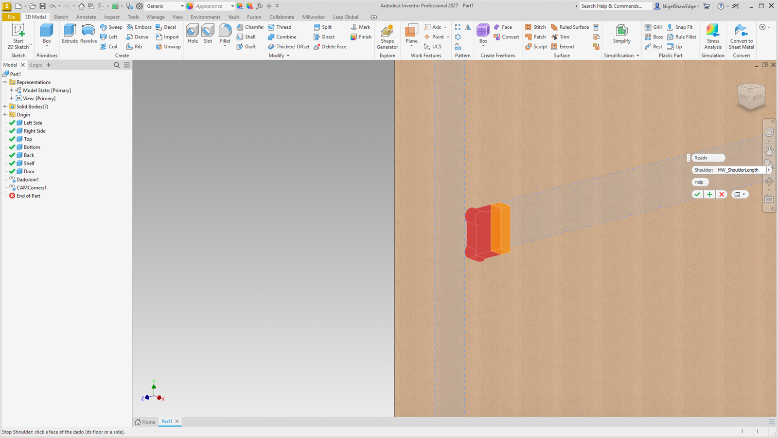
The dado is filled that far in from the end, and any part running in the dado there is notched to suit. The notch is longer than the shoulder by CAM_RADIUS × 1.5, so the cutter's round end clears it. Parameter: MW_Shoulder#_Length.
 Edge Inset
Set panel edges back by a small inset, for reveals or edgebanding allowance.
- A part with panels whose edges should sit back from the face of the cabinet.
- Click Edge Inset.
- Click edge faces. What is cut off previews in red.
- Set the Inset (starts as
MW_EdgeInset, 0.02″). - Apply or OK.
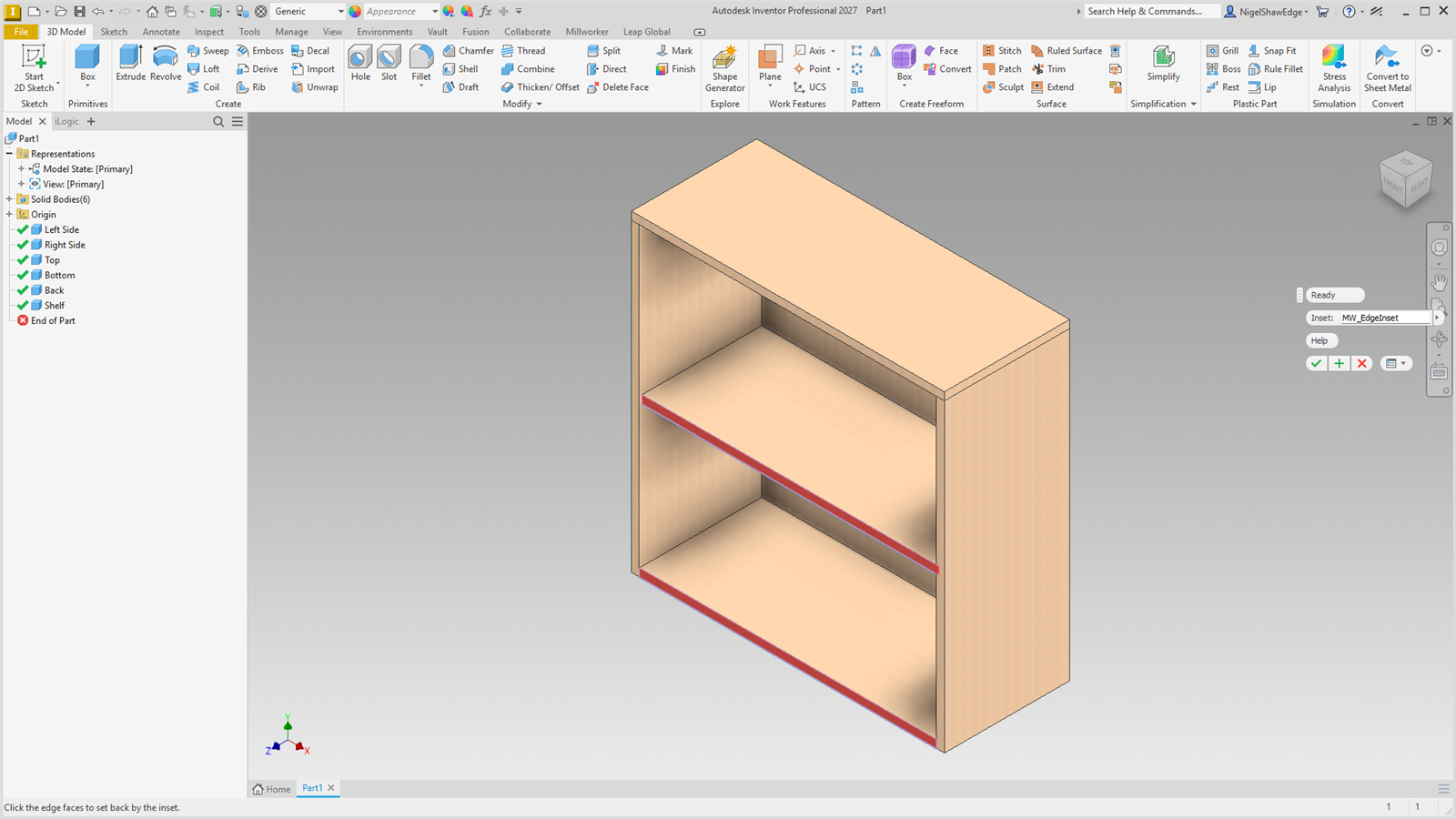
Each edge is set back by a thicken that cuts into its panel. Parameter: MW_EdgeInset#_Inset.
 CAM Corners
Dog-ear the square inside corners a round CNC cutter cannot reach, so square parts fit.
- A part with slots, notches, pockets or halvings that will be cut on a CNC router.
- Click CAM Corners.
- Click the panel faces the cutter comes in from (several; click one again to take it back). Every square inside corner running from that face previews in red.
- Check the Radius (the part's
CAM_RADIUS, 1/8″, for a 1/4″ cutter). - Apply or OK.
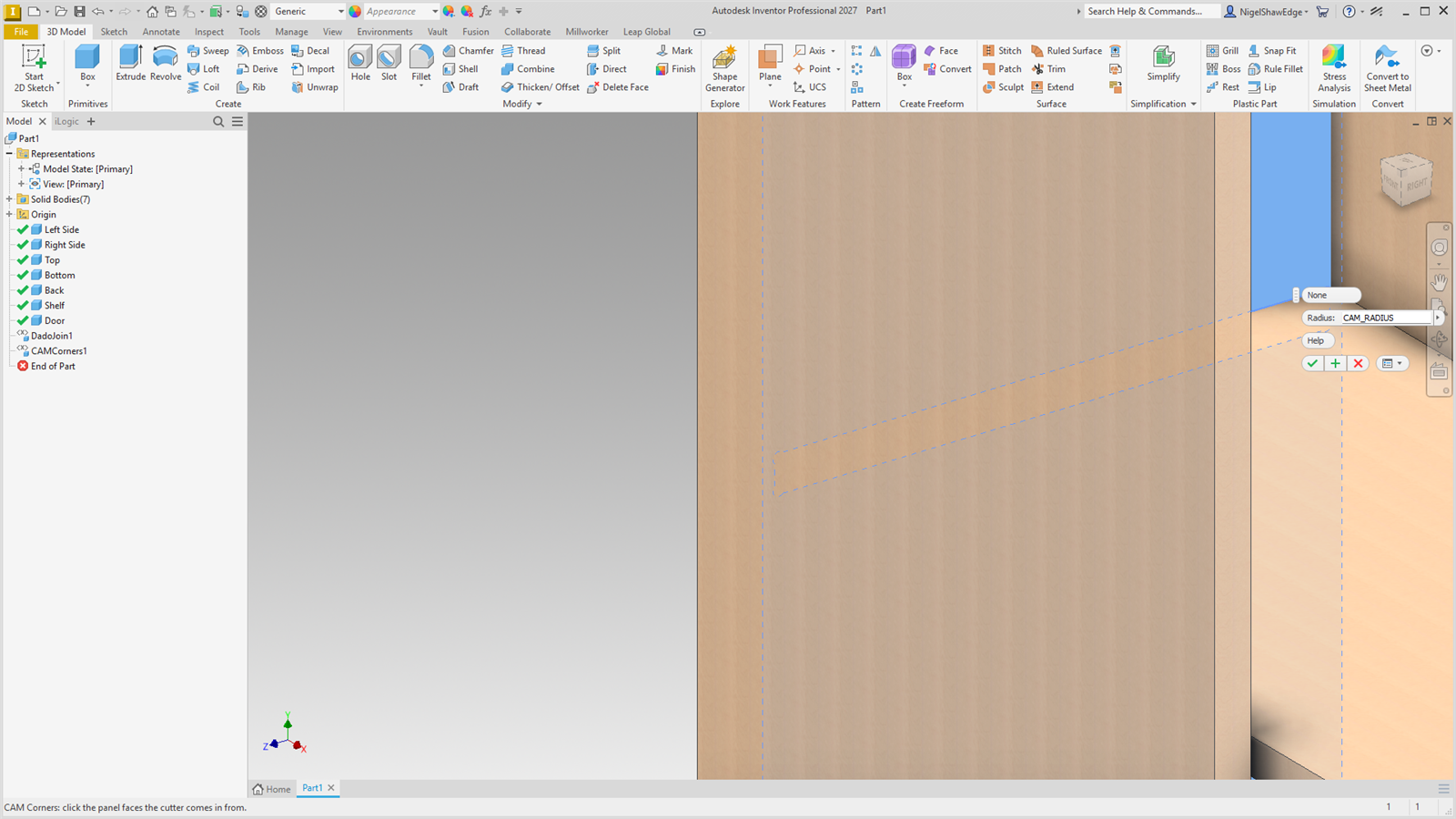
Each dog ear is a round cut of the radius, its centre the radius from the corner into the open side, so it runs through the very corner. A pocket's floor is not cut into. One node per face; double-click it or change MW_DogEars#_Radius to change it. Dado Join, Halving and Stop Shoulder add CAM Corners for you.
 Hinge Holes
Bore concealed (35 mm cup) hinge holes in a door, and the plate holes in the cabinet side.
- A part with a door and the cabinet side it hangs on, as solid bodies.
- Click Hinge Holes. The sizes popup opens (also on Settings…).
- Click the door's inside face, then its hinge edge, top edge and bottom edge (each an edge or the edge's face). The cups preview as red cylinders.
- With Plate holes ticked on the toolbar (the default), click the side's inside face too. Untick it for the hinge holes only, door by door: it's remembered for next time (the same tick is in Settings, Drill plate holes in the cabinet side).
- Apply, or click the next door's face to carry on, or OK.
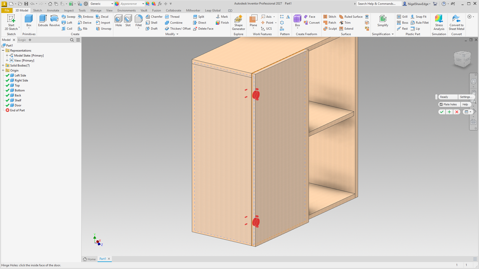
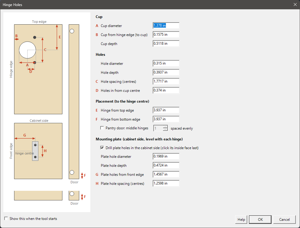
| Size | Default | |
|---|---|---|
| A | Cup diameter | 35 mm (1-3/8″) |
| B | Hinge edge to the cup | 4 mm |
| Cup depth | 13 mm | |
| Screw hole diameter / depth | 8 mm / 10 mm | |
| C | Screw hole spacing | 45 mm centres |
| D | Screw holes in from the cup centre | 9.5 mm |
| E, F | Hinge centre from the top / bottom edge | 100 mm (about 4″) |
| Pantry door: middle hinges | Spaced evenly between top and bottom | |
| G | Plate holes in from the side's front edge | 37 mm |
| H | Plate holes apart | 32 mm (5 mm × 12 mm deep) |
Lengths take units (35mm, 1.5in; the tool unit when none). Every hole is dimensioned to the picked edges, so when the door or side changes size the holes follow, with no Update. Double-click the node to change sizes; Update all hinge holes in this part does every hinge node at once. The cups are tagged for Place Hardware.
 Shelf Holes
Drill rows of 5 mm shelf pin holes up a cabinet side, on a 32 mm pitch from a shelf.
- A part with a cabinet side and an adjustable shelf (its edge against the side sets where the holes start).
- Click Shelf Holes. The sizes popup opens.
- Click the side's inside face, then its front edge, back edge and the shelf edge (where the shelf meets the side, or the shelf's face against it).
- Choose the rows, holes per row and which way the pattern runs. The holes preview in red.
- Apply or OK.
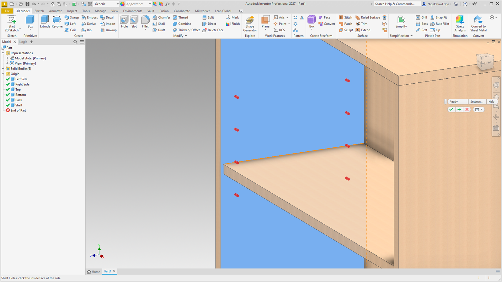
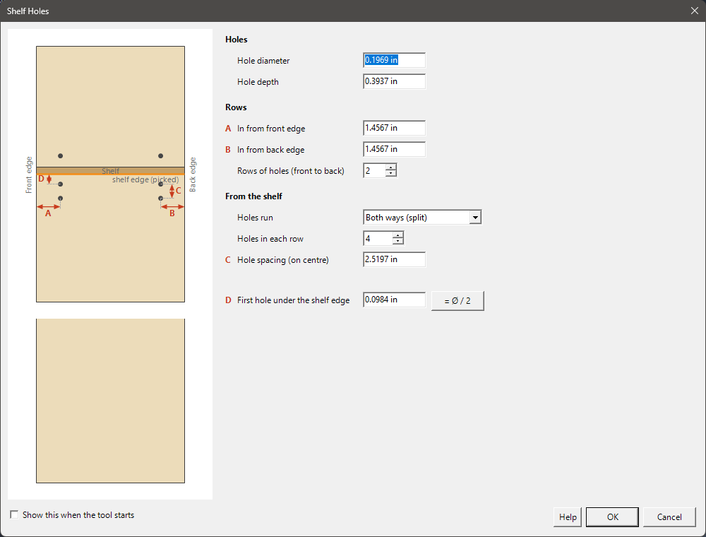
| A, B | In from the front edge and back edge: 37 mm. |
| Rows | 2, or more spaced evenly between. |
| Direction | Up from the first hole, Down from the first hole or Both ways (the odd hole goes up). Up is up in the view when the shelf edge is picked. |
| C | Hole spacing on centre: 32 mm. Any spacing that is not a multiple of 32 mm is flagged red, and OK asks first. |
| D | First hole from the shelf edge: 0 puts it on the shelf line. = Ø / 2 sets half the hole diameter, so the hole's edge just meets the shelf. |
| Hole | 5 mm × 10 mm deep. |
Each centre is dimensioned to the projected edges and the shelf edge, so moving the shelf or resizing the side moves the holes with it. The node keeps its shelf edge. The last sizes used are kept for next time.
 LED Channel
Grooves for LED tape along a face's edges, joining cleanly at corners.
- A part with a panel that takes LED tape: the underside of a wall cabinet bottom, a shelf, a toe kick.
- Click LED Channel (Features panel).
- Click a face, then each edge of it a channel runs along (one channel per edge). Click another face to go on there.
- Set Width, Depth and Offset (in from the edge). Ends in 0 runs the channel out at both ends; a larger value stops it that far in.
- Apply or OK.
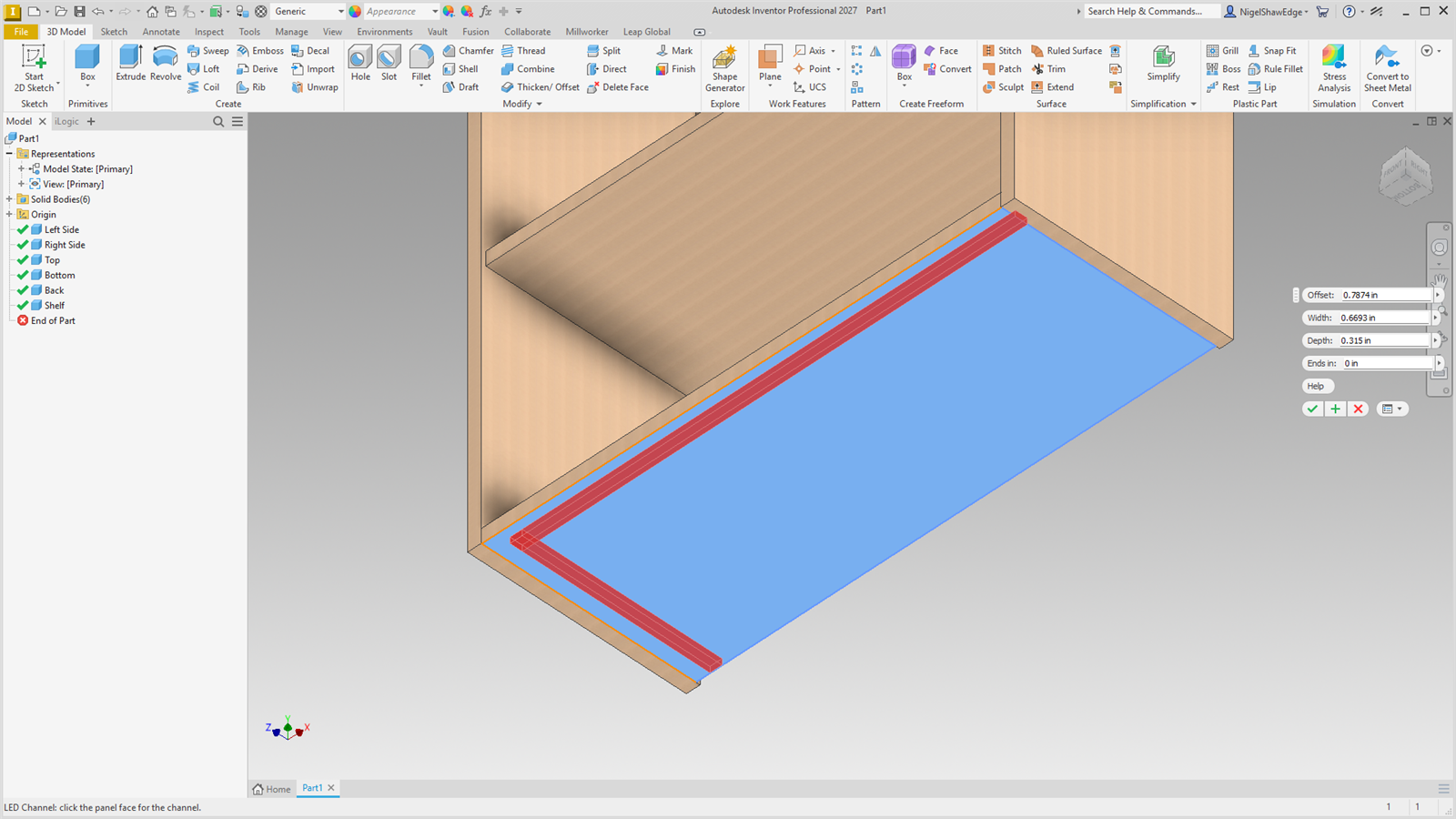
Where two picked channels meet at a corner, each stops level with the other's outer side, so they join into one corner instead of crossing. The sketches sit hidden inside the node.
 Edge Profile
Round-over, chamfer, cove, ogee and your own profiles along edges, with a profile editor.
- A part with a top, shelf or door whose edges get a profile.
- Click Edge Profile (Features panel).
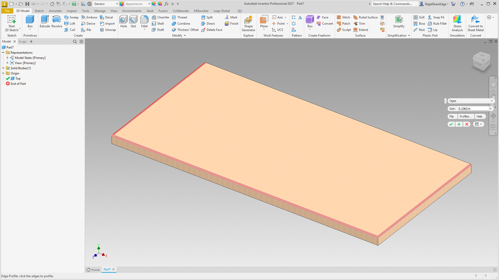
- Click edges and choose a profile. Each cut previews in red.
- Set the Size; Flip swaps which face a drawn shape starts on.
- Apply or OK.
Profiles
- Round-over and Chamfer are Inventor's own fillet and chamfer, Size the radius or distance.
- Cove, Ogee, Roman ogee, Bevel 30°, Rabbet, Step round-over and your own are drawn shapes swept along each edge. Size scales them. A drawn shape starts on face A, the larger face at the edge.
- Click one edge and the profile follows every edge running on from it without a corner: round a rounded corner, along the next side and round the next, until a square corner. Profiles meeting at a corner meet as a router leaves them.
- A drawn profile (Cove, Ogee, your own) starts at a straight end of the run with a square corner. An edge that goes all the way round with no corner (a round top) takes Round-over or Chamfer.
Changing a profile
Double-click an Edge Profile node. Choose another profile, its size and Flip; OK makes the node again on the same edges, keeping its name and size parameter.
The profile editor
Profiles… opens the editor, maximized. Built-in profiles are read only: Copy one to make your own, or New for an empty one. The panel's corner is at the bottom left, face A along the bottom and face B up the left; the bar at the top says what to click next.
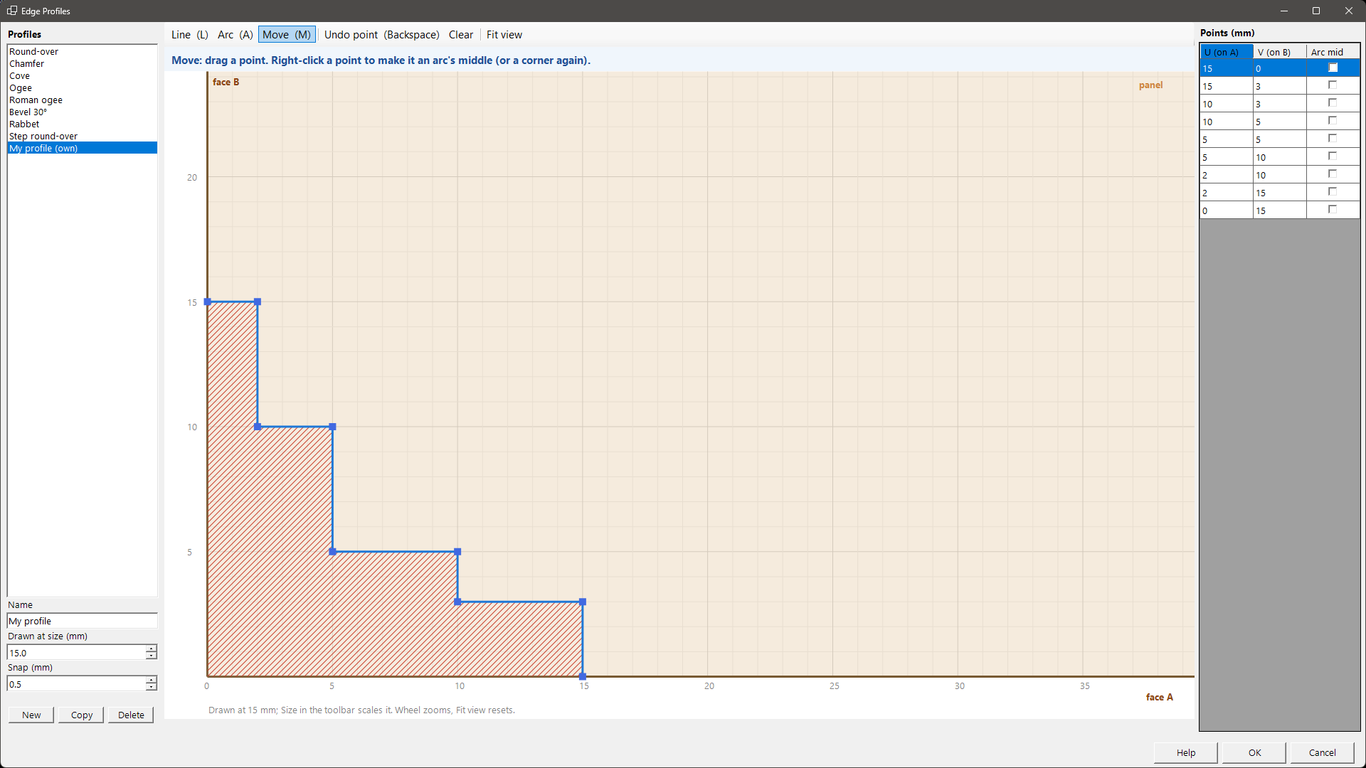
| Line (L) | Click where the profile starts on face A, then each next point. Click on face B to finish. |
| Arc (A) | Click a point the arc passes through, then its end. |
| Move (M) | Drag points (ends stay on their faces). Right-click a point to make it an arc's middle or a corner. Delete removes it. |
| Undo point | Backspace. Esc drops a half-drawn arc; Clear starts again. |
| View | The wheel zooms; Fit view resets. Points snap to the grid and onto the faces. The table on the right takes exact values. |
Your profiles are kept in Millworker Edge Profiles.json next to the material database, so every PC has them.
Treatment
 Shaker Door
Split a door slab into a 5-piece shaker door: stiles, rails with stub tenons, and a floating panel.
- A part with a door slab as a solid body, at the door's finished size and thickness (3/4″).
- Click Shaker Door (Treatment panel).
- Click the door's front face.
- Check the sizes in the toolbar. Rotate 90° puts the stiles on the short sides, for a door lying sideways.
- OK.
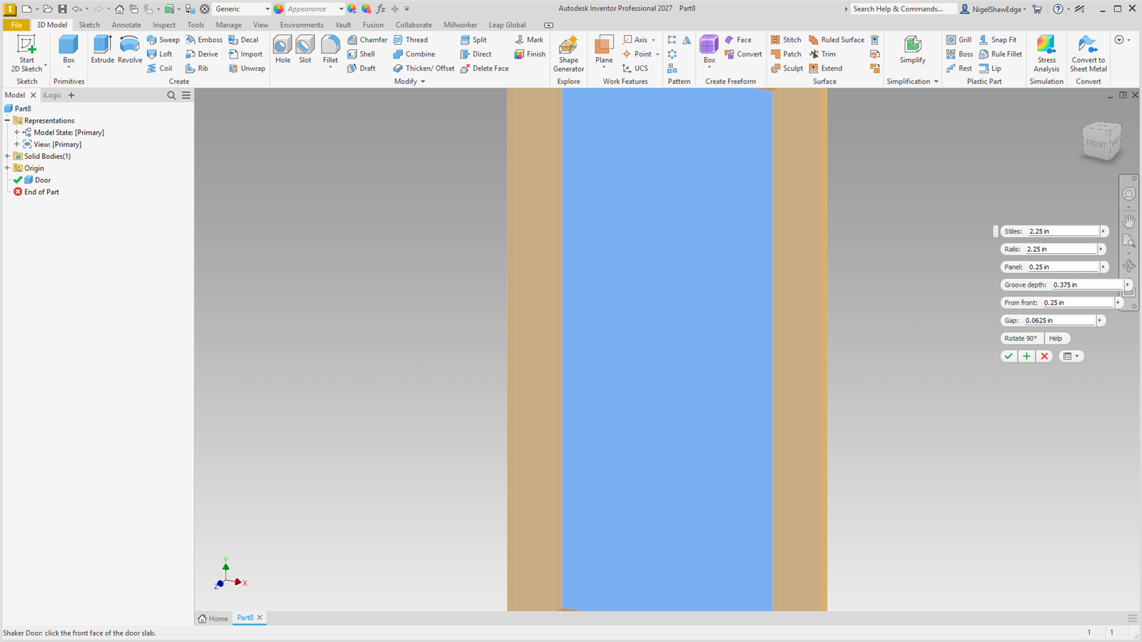
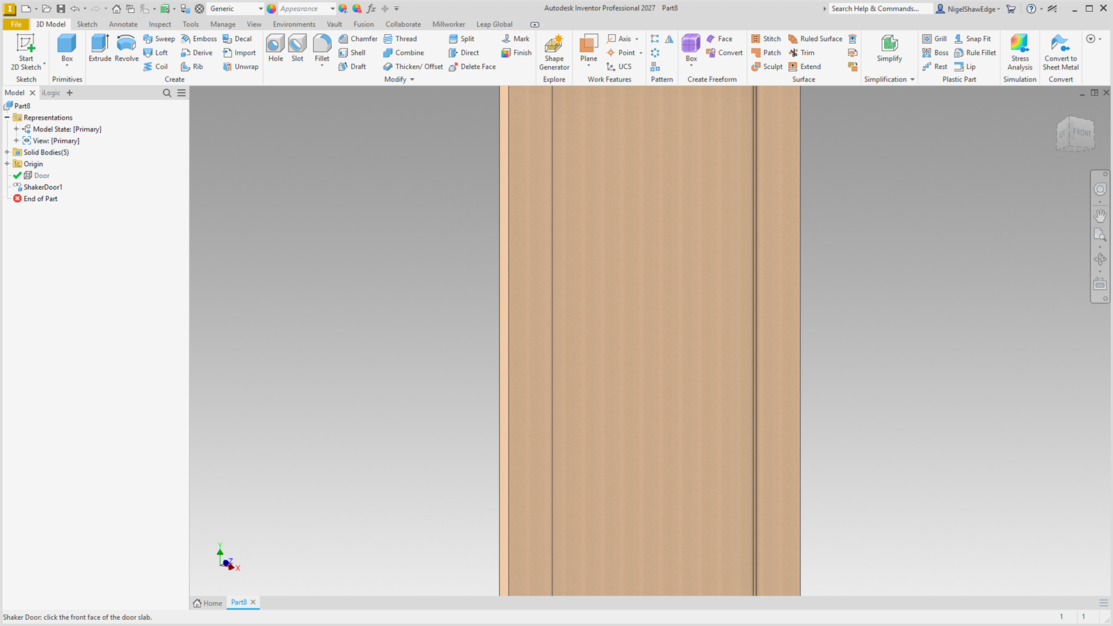
| Value | Default |
|---|---|
| Stile and rail width | 2.25 in |
| Panel thickness | 0.25 in |
| Groove depth | 0.375 in |
| From front | 0.25 in (the groove's distance back from the door's front) |
| Gap | 0.0625 in (the panel stops this short of the groove bottoms) |
The slab is split into two full-height stiles, two rails between them and the centre panel. Every member gets a groove on its inside edge, the panel's thickness plus the dado clearance wide. The rails get stub tenons into the stiles' grooves. The panel is thinned to its thickness and grows into the grooves.
 Lattice
Turn a body into slats, or groove and flute it, with a width and spacing that follow its length.
- A part with a body to make into slats: a slatted panel, a grille, a fluted door.
- Click Lattice.
- Click a body. Choose X, Y or Z, the direction the slats are spaced along.
- Set the slat Width and Spacing (the gap). The gaps preview in red. A Spacing of 0 splits the body into its slats.
- Tick Machined to make every slat flat and square: for a curved or shaped piece cut into strips with machined edges.
- Leave Through ticked to cut right through, or untick it and give a Depth for a grooved or fluted panel (Flip cuts from the back face).
- Apply or OK.
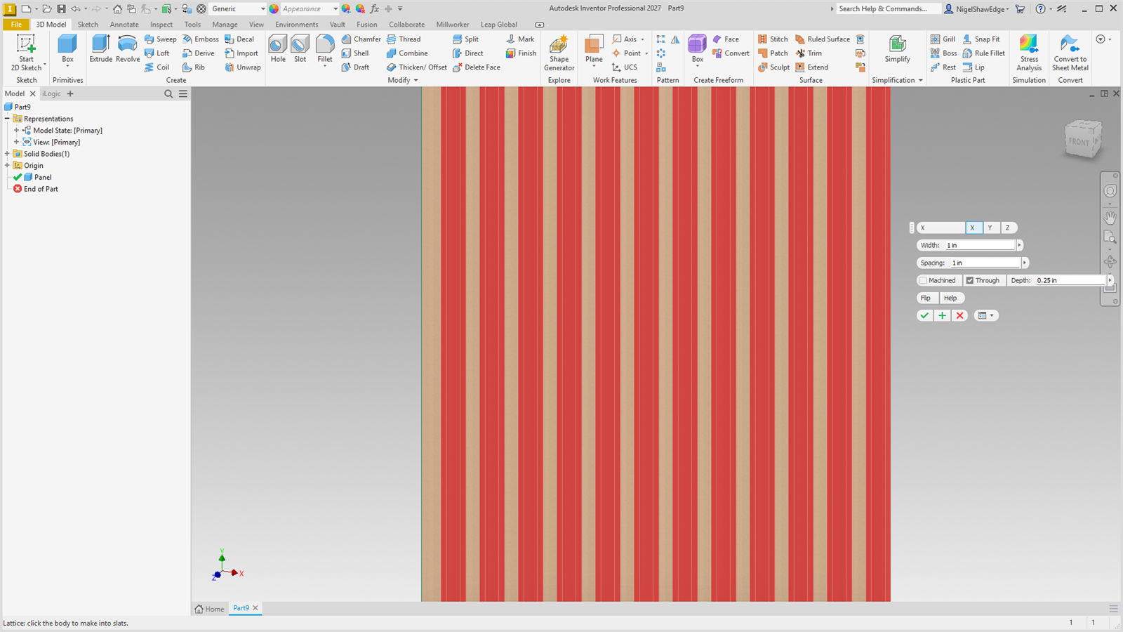
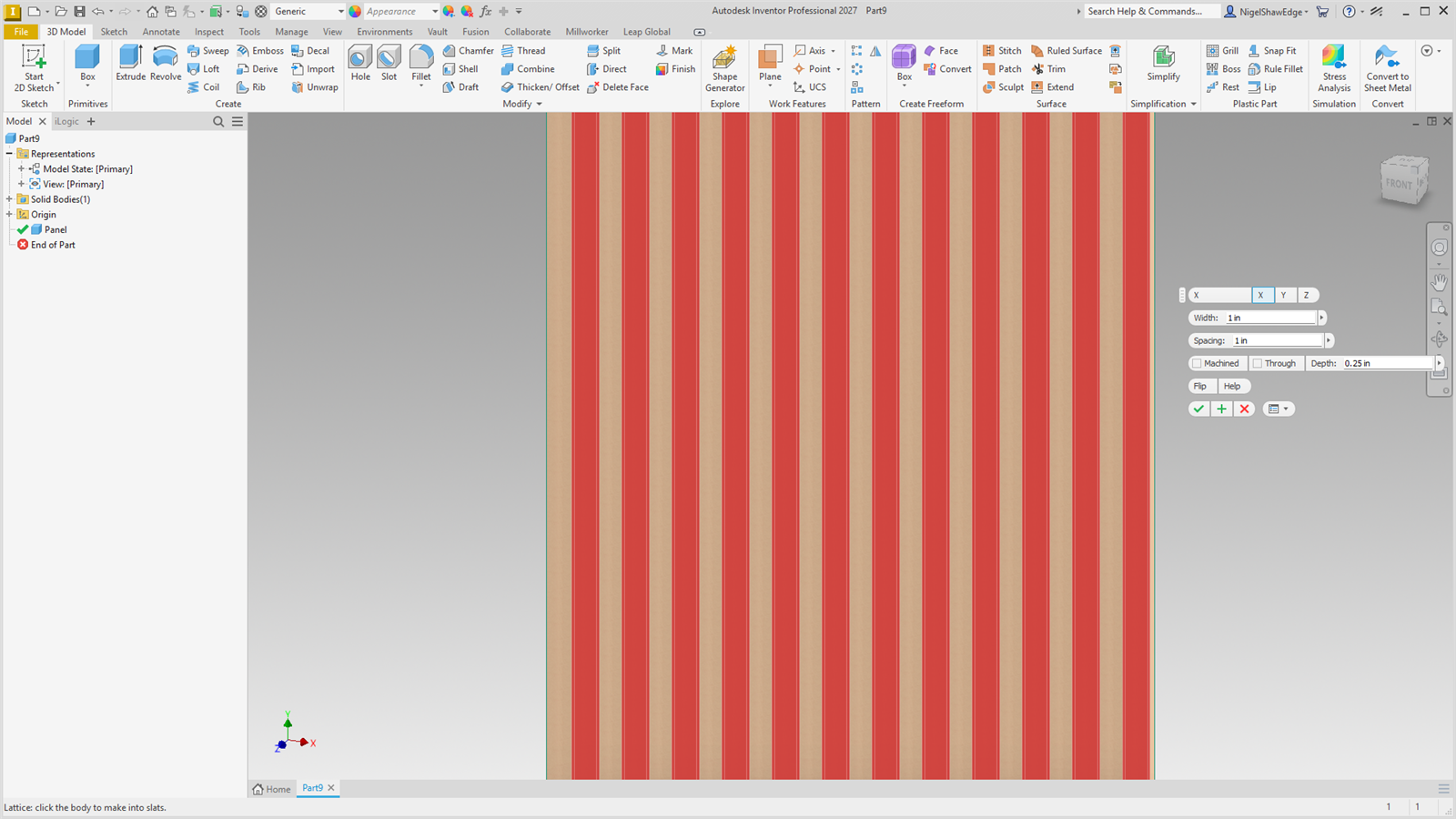
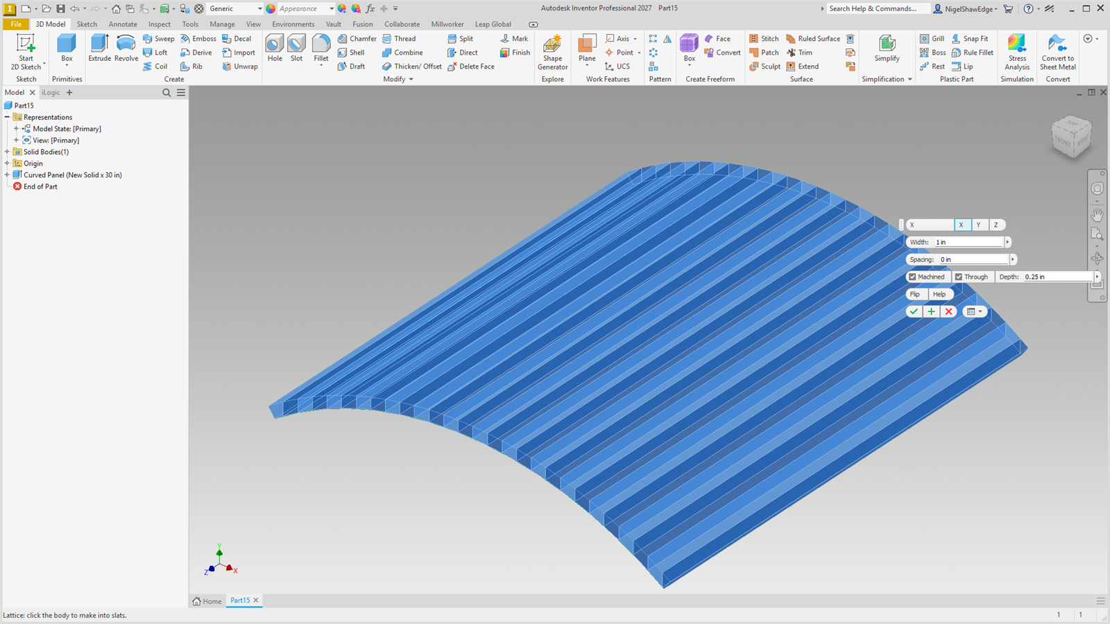
From the body's start: a slat the width, a gap the spacing, and so on, patterned as many times as fit, so changing the width, gap or the body's length changes the slats. The slats stay one body of separate pieces; Split Out makes them bodies of their own. Double-click the node to open the tool again with everything as it was, or move it to another body.
No gap, and machined slats
With a Spacing of 0 the body is split into its slats, each a body of its own (body Slat 1, Slat 2 and so on). With Machined ticked, each slat is the piece's section at the slat's middle, extruded the slat's width both ways, so every strip is flat with square, machined edges, however the piece curves; the piece itself becomes the first slat. Both count the slats when they are made, so a new width or a longer piece makes them again (double-click the node: the piece shows again while the tool is open, and Cancel puts the slats back). The planes and sketches they are built on are construction planes, out of the browser.
 Sunburst
Turn a body into slats set out along curves (an arc, or a seat's profile curving either way), the same width all the way, the gaps tapering.
- A part with a body to make into slats: a half-round or arched panel for a sunburst, or a panel cut to a seat's profile; flat for the CNC.
- The curves to set the slats out along, in one plane and joined end to end: arcs and lines, edges of the body or curves in a sketch. One arc gives a sunburst; arcs curving either way, with lines between, give a seat. Not a full circle.
- Click Sunburst (Treatment panel).
- Click the body (only bodies can be picked at first). Then click the curves one after another, in any order (now only edges and sketch curves can be picked); click a curve again to take it back. Body starts again with another body.
- Set the slat Width and the Spacing: the smallest gap anywhere, where the slats come closest. Click Preview to see the slats in blue and what comes out between them in red (it is not worked out while you pick).
- Apply or OK.
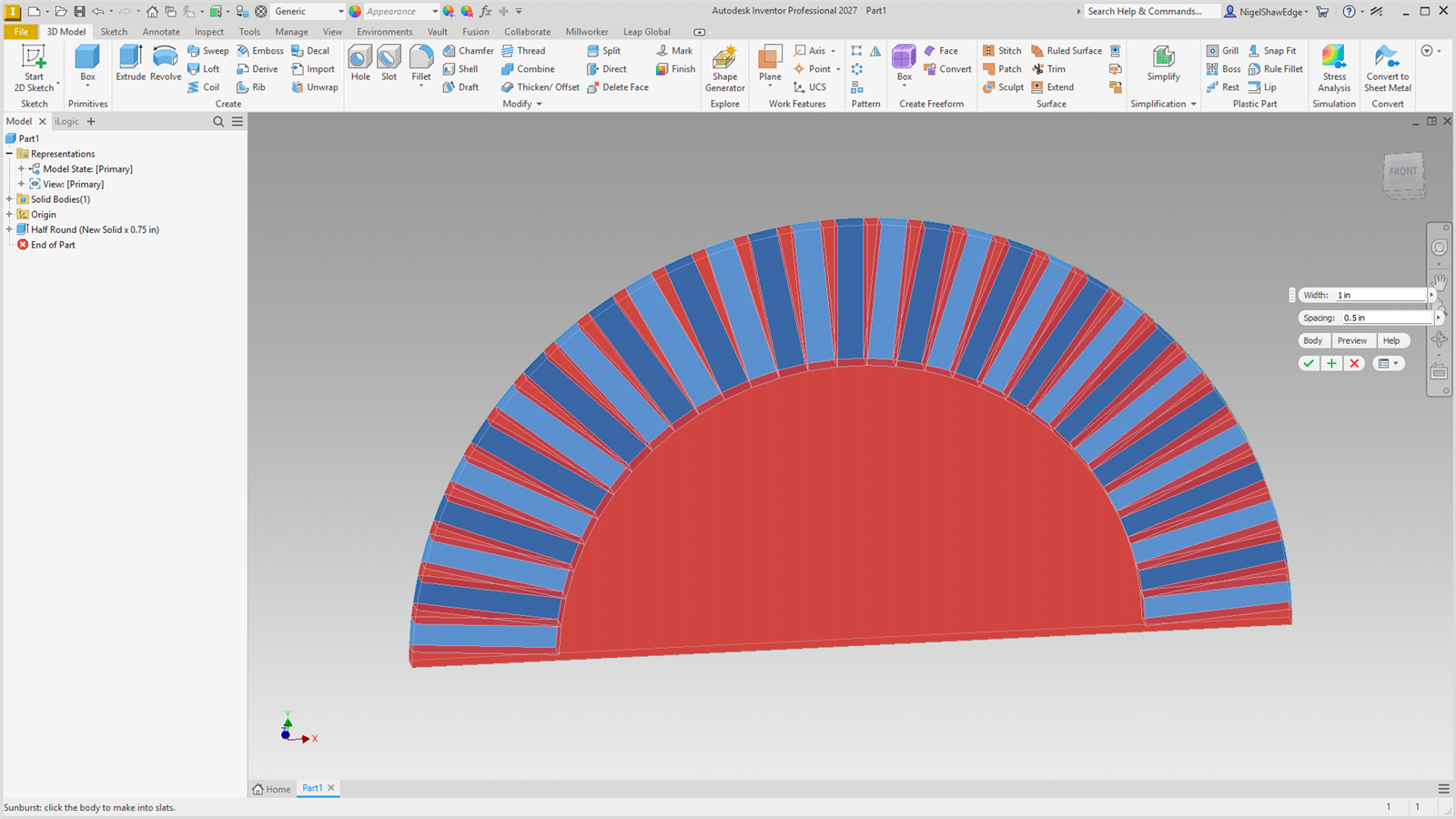
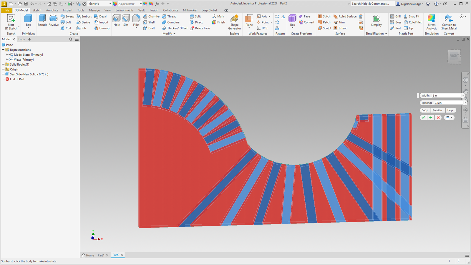
Each slat is square to the curves at its middle and keeps its width all the way along, so the gaps between them taper. Each curve gets its own spacing, set where its slats come closest so they never touch: inside a bend that is the far side of the piece towards the bend's centre (the back of a seat), where the gap is the Spacing, opening out from there; along a line the slats are parallel, the Spacing apart. Each slat sits in the middle of its share of the curve, the lot centred on it. Only when the piece reaches round the bend's centre itself (a sunburst's half-round) are the slats spaced at the curve instead and trimmed off square where they meet.
Each slat is made as a machined one: the piece's section on a construction plane through the slat's middle, extruded the slat's width both ways, so every slat is flat with square edges. The piece itself becomes the first slat; each slat is a body of its own (body Slat 1, Slat 2 and so on). The planes, sketches and slats are all in the Sunburst node. Parameters: MW_Sunburst#_Width and _Gap; for each arc _P#Inner (how close the piece comes to its centre, measured when made), _P#Pitch (the angle between slats, worked out from them), _P#Sweep and _P#Ref; for each line _P#Length and _P#Ref. The slats are counted when made, so a new width or spacing makes them again: double-click the node (the piece shows again while the tool is open, and Cancel puts the slats back).
 Split Out
Make each separate lump of a body into a body of its own.
- A body made of separate lumps, for example the slats a Lattice left in one body.
- Click Split Out.
- Click the lumps (a click anywhere picks the whole lump, lit all over), or tick All lumps and click the body.
- OK.
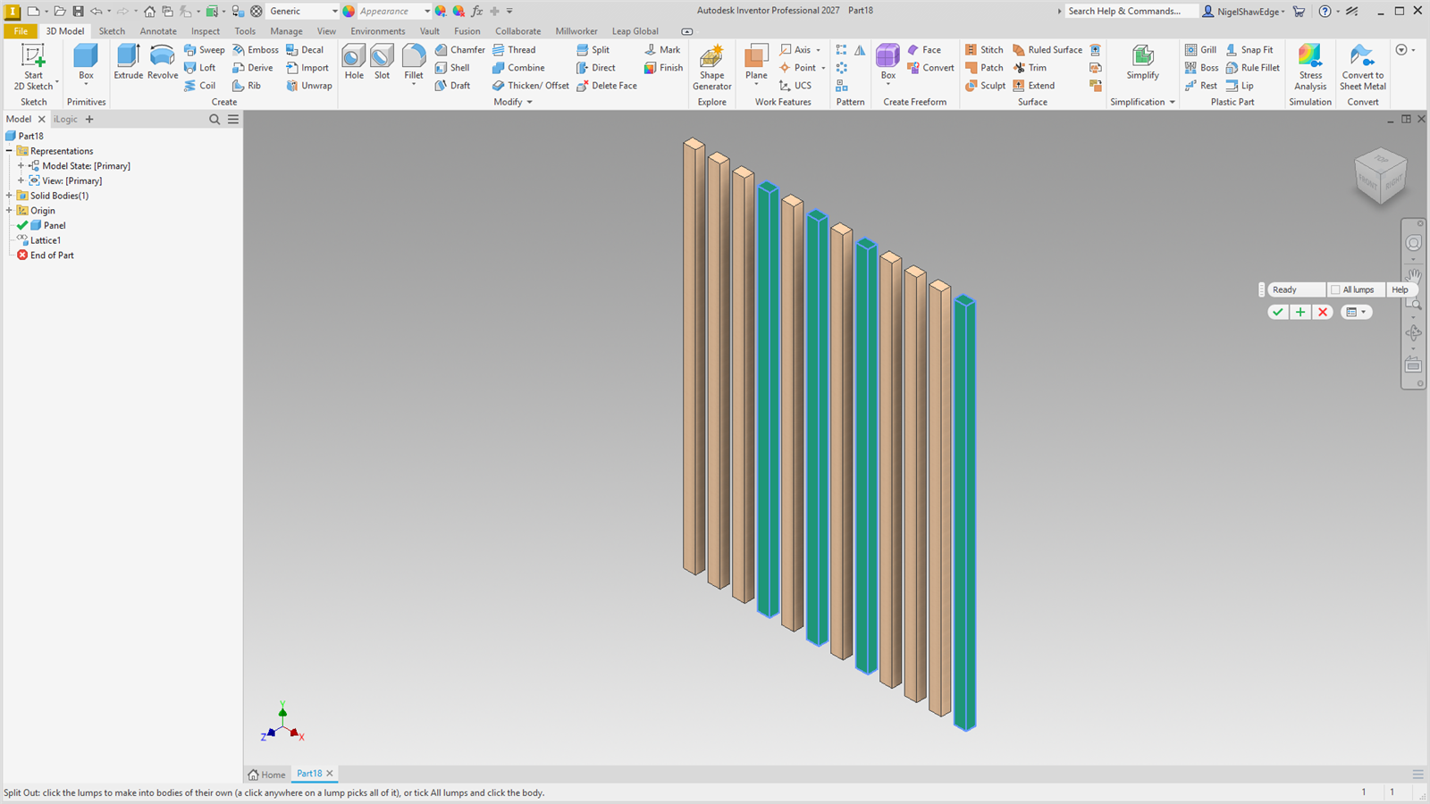
Each picked lump becomes a body of its own and is cut out of the original body. At least one lump stays in the original. Lumps that interlock (one inside another's box) can't be split out this way. The new bodies are not parametric; delete the node to put the lumps back.
 Copy Body
Copy bodies a distance along X, Y or Z, along an edge at an angle, or along a curve, as many times as you need, kept editable.
- A part with a body to repeat: a shelf, a divider, a drawer front.
- Click Copy Body.
- Click bodies.
- Choose the direction with X, Y, Z and Flip. A triad at the first body shows it, the chosen arrow long.
- To follow a curve, press Path and click it: an edge (a rounded edge, a circle) or a sketch or 3D sketch line, arc or spline (the sketch has to be visible; joined sketch curves are followed on). The copies start from the end nearer the first body, measured along the curve; Flip starts them from the other end. Rotate (on to start) turns each copy with the curve; off, they all face the same way. Fill spreads the copies evenly over the whole path (round a closed curve, evenly all the way round) and the distance isn't used. X, Y, Z, Edge or Part go back to a straight direction.
- Set the Distance (each copy from the one before, along the curve on a path) and Copies (how many). The copies preview in blue.
- Apply or OK.
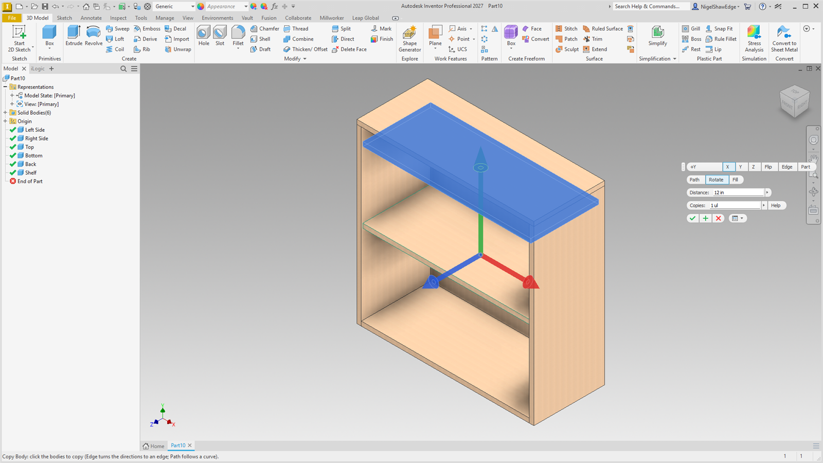
It is a rectangular pattern of the bodies (the copies and the bodies, as new bodies) along the part's axis, the edge or the path, in a CopyBody node. Along Y or Z of an edge it uses a hidden work axis tied to the edge and its face, so the copies follow if the body moves. Parameters: MW_CopyBody#_Distance and MW_CopyBody#_Copies.
 Waste Envelope
A sized oversize box round each body for rough stock, shown in yellow and listed on the cut list.
- A part with solid-wood or rough-stock bodies that need cutting oversize before machining.
- Click Waste Envelope. Every body that has one shows its yellow see-through box.
- Click a body to give it one (the oversize from Millworker Settings on each end and side), or click again to take it off the display.
- Ends, Sides and Faces set both sides of every shown envelope; drag a side of a yellow box to size that side alone (to 1/32″).
- Apply or OK keeps them; Clear takes them off the shown bodies.
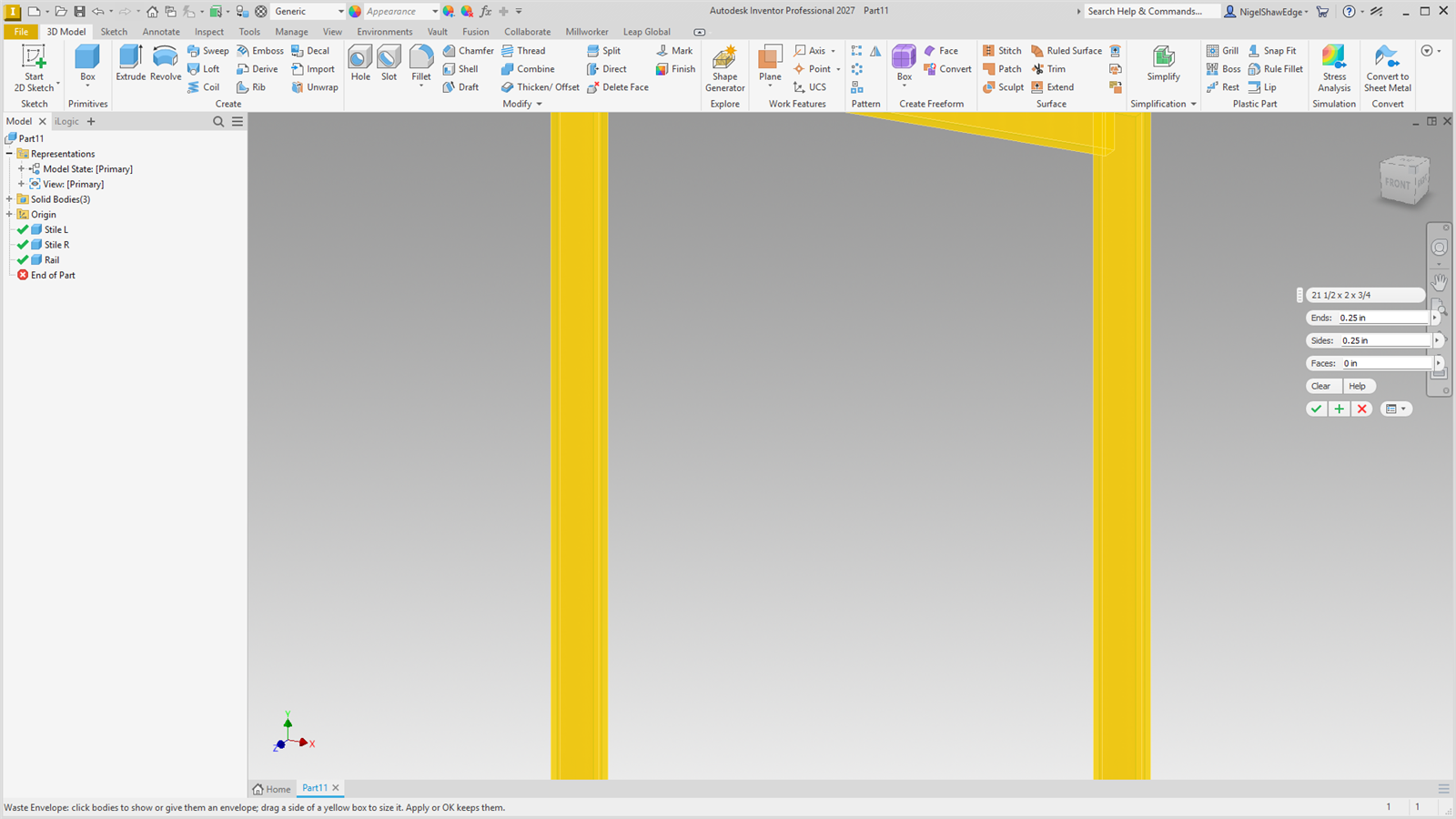
The envelope does not change the body; it is kept with it (L1, L2, W1, W2, T1, T2 oversizes and the envelope's length, width and thickness). The cut list and reports have Envelope L, Envelope W and Envelope T fields to add as columns.
 Make Flat
Flatten curved wood panels: see the panel and its proposed flat side by side, sized from the panel, and save it as its wood flat.
- An assembly (or a part) with curved panels: an even-thickness bend, like a radius door or a curved end panel.
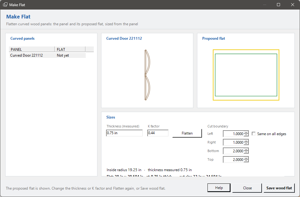
- Flat panel → Make Flat. A window opens beside Inventor and stays open while you work.
- The window lists the model's curved panels: Flattened ✓ (green), Not yet, Didn't unfold (red), or Out of date (orange: the panel changed size after its flat was saved). In a part, the part itself is the panel.
- Pick one in the list, or press Pick in model and click it in the assembly. It lights up in the model.
- The window shows the panel (looking down its bend) beside its proposed flat, green when it flattens. Nothing is added to the model.
- Under them are the sizes taken from the panel: Thickness (measured), the inside radius, the K factor (where the neutral layer sits through the thickness; 0.44 suits most wood) and the flat length and width. Change the thickness or K factor and press Flatten (or Enter).
- Cut boundary adds stock round the flat for cutting it out, a box for each side, stacked: Left, Right, Bottom and Top (as the flat is drawn). Tick Same on all edges beside the Left box and it sets all four. As you change them, a yellow line shows the boundary round the flat, and the cut size shows beside the flat size. The last boundary you saved is where the next panel starts.
- Save wood flat keeps it. Save the panel (or the assembly) to keep the link.
There's no sheet metal to set up. Make Flat keeps a part out of sight, <panel> WF.ipt beside the panel, that derives the panel (it follows changes to it) and is unfolded at the thickness and K factor shown. The panel gets the iProperty MillworkerWF = WF (add it to labels and reports to flag the panel), and NestCAM nests the flat instead of the curved panel.
The cut boundary is built into the flat part, so its flat pattern is the size to cut: a 25" x 25" flat with 1/4" on each side is 25 1/2" x 25 1/2". It's driven by the parameters MW_CutLeft, MW_CutRight, MW_CutBottom and MW_CutTop in the flat part (with Same on all edges, the other three follow MW_CutLeft).
In drawings, Show Flat places a panel's flat, and the Drawing Builder gives each flattened panel a sheet with its flat.
Materials
 Material Manager
The shop's materials, edgebands, veneers and finishes in one shared database: a manager only.
- An assembly of panel parts. Millworker tab → Materials → Material Manager.
- A drawing. Millworker tab → Callouts → Material Manager.
- The first time, it asks for the material database folder (also in Settings).
Everything is kept in a shared SQLite database, Millworker Materials.db. Every change is saved straight away.
A manager only. Nothing is put on parts from here: Materials Finishes does that, and is usually the first step (most of the time you won't need the manager at all).
Codes come from MatFin. The parts, the drawing's callouts and the tags all get the code from the project's MatFin workbook (its EWC code). The Material Manager's Default code (and an edgeband's Edgeband code, EB-1…) is never used: Push to MatFin shows it in the workbook's DEFAULT CODE column, and Reference Tables shows it on the row, for reference. To use it, type it in the row's EWC code. Until the workbook has a row for an item, its code is blank.
Pictures: set your textures and finishes folder in Millworker Settings (Textures folder), and Image… opens there. A picture chosen from inside it is kept by its path in that folder (WoodWalnut.jpg), not copied, so when the folder moves to another drive or server, change the setting and every entry finds its picture again: by the same path, else by the same file name anywhere in the new folder. A picture from outside the textures folder is kept by its full path. With no textures folder set, a picture is copied into the database’s Images folder, as before.
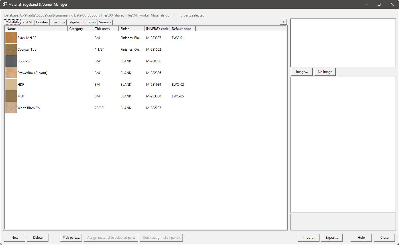
Materials
Name, category, thickness, the optional INNERGY code and INNERGY material (the nest's stock code, and the SKU that links it to each project's MatFin workbook), Default code (shown in MatFin, not used), grain, sheet size, the library material it starts from (Start from material), notes and a picture. The part's Inventor material is named after the INNERGY material when there is one, else after the material's own name.
A material also has a finish: Finish type (BLANK, Veneers, or a finish tab) and Finish. When Materials Finishes puts the material on a part, the material goes on the body and its finish, if it has one, on the part's two largest faces. New, Delete and Image… are at the top.
PLAM
Plastic laminates, on their own tab after Materials. A PLAM has the same settings as a material (name, category, thickness, INNERGY code, Default code, INNERGY material, grain, sheet size, Start from material, notes and picture) but no finish on its faces: the laminate is the finish. Materials Finishes puts it on as the parts' material, and takes any finish off their large faces.
Looking up INNERGY codes
Click an INNERGY code or INNERGY material box on a material or PLAM, an Edgeband code, or a veneer's INNERGY code, then click its … button. The Find in INNERGY window searches the INNERGY material library by name or SKU (every word you type must match), and you can narrow it to one INNERGY category. It starts on the category that fits (P-lam for a PLAM, edges for an edgeband, and so on). Pick a material and click OK, or double-click it. Its SKU goes into the code, and its name goes into INNERGY material; a Face 2 code takes the SKU only. On a material or PLAM, the INNERGY custom field micValue (the sheet’s actual thickness, 0.728 for an “18mm” sheet) goes into Thickness when the INNERGY material has one. Each time the Material Manager opens, every material and PLAM with an INNERGY code takes its micValue the same way (the header names any it changed), so a value changed in INNERGY comes in after Fetch again. A library fetched before this was kept is fetched again the first time. The library is fetched once with your INNERGY login (Settings, References tab) and kept; Fetch again reloads it. All of this needs Use INNERGY ticked in Settings, References tab; with it unticked the codes are typed in by hand and thickness isn't changed.
Edgebands
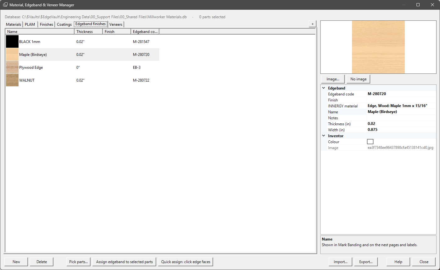
Name, thickness, width, finish, INNERGY code, INNERGY material, Edgeband code (EB-1…, a default shown in MatFin, not used), notes, a woodgrain picture (drawn with its length horizontal) and a colour for when there is no picture. These are the band list for Mark EdgeBand and the nest.
Veneers
Name, species, cut, thickness, Grade (the panel grade: face letter and back number, A1 is an A face and a 1 back; Face 1 takes the letter, Face 2 the number), Default code (the shop’s code, VEN01, for reference: it shows in MatFin’s DEFAULT CODE column, and the MatFin code is the one used), INNERGY code, INNERGY material and picture (grain horizontal). A veneer is a single leaf with one code; a layup puts one veneer on each face, the same or two different. In MatFin a veneer is a MATERIAL row with sub type VENEER, numbered VEN01, VEN02… A veneer goes on as a material's finish, or with Materials Finishes (finish type Veneers). NestCAM lays Face 1 up on the sheet. The grades offered are every face grade with every back grade in Millworker Settings, General tab, Veneer (face A, B, C; back 1, 2, 3 to start).
Finishes
Finishes, Coatings and any tab you add with + (stains, laminates…). Each finish has a name, kind, Default code (shown in MatFin, not used) and the Inventor appearance that shows it. A finish has no INNERGY code or description of its own: those come from the material. It is linked to each project's MatFin workbook by its name: that row's EWC code is its code in the project. Push to MatFin brings finishes in without an INNERGY SKU. A material's Finish type and Finish put that finish on the parts' two largest faces when the material is put on. A material whose Finish type is BLANK takes any finish off the large faces (their appearance override is removed), so they show the material; banded and veneered faces keep theirs.
When an entry goes on a part
With Materials Finishes (or Mark EdgeBand for edgebands):
- A material is made in each part, copied from its library material, with an appearance from the entry's picture. Pictures run along the panel's marked grain (or its longest edge).
- An edgeband replaces the band on each part's banded faces.
- A finish takes every look the part had off first (its own, its bodies', features' and faces'), then puts the finish on the whole part, every face. The two large faces are marked with it (cut lists and codes). Banded and veneered faces keep their own look.
- The project's codes (from MatFin) go on with them: each part gets the codes as custom iProperties (
MillworkerMaterialCode,MillworkerFinishFace1Code,MillworkerFinishFace2Code,MillworkerCoatingFace1Code,MillworkerCoatingFace2Code,MillworkerEdgebandCode,MillworkerVeneerFace1Code,MillworkerVeneerFace2Code) and the material's name asMillworkerMaterial; banded, veneered and finished faces carry their code too. - The Inventor material made in the part and assigned is named after the entry's INNERGY material when it has one (as InvInnergy names it), else after the Millworker material. Either way it has the entry's picture and its Start from material's physical properties. NestCAM reads this name.
- The part shows the material's look: an appearance set over the whole part (a template's “SEE FINISH SCHEDULE”, say) is taken off, and bodies and features with their own appearance follow the part. Faces with a finish, veneer or edgeband keep theirs.
- After Push to MatFin's Save, every part in the assembly is given the workbook's codes straight away.
Sharing
Export… writes everything to a .mwmaterials.json file; Import… adds the entries from one, matched by name (it asks whether to update names already in the list). Export also copies every picture into a <file name> pictures folder beside the file: keep it with the file. Import brings in each picture this database can’t already find (in the textures folder or its Images folder) from that folder, and says if any are still missing.
 Materials Finishes
Assign a material or finish to parts from a mini toolbar, without opening the manager.
- An assembly (or a part, where the part itself is the pick). Materials panel → Materials Finishes.
- Choose Material or Finish in the first list; the other list is greyed out.
- For a material, choose it. For a finish, choose its type first (Finishes, Coatings, a tab you added such as Paints, Veneers or PLAM), and the finish list shows only that type.
- Click parts (or drag a window). Click a picked one to take it out. Parts selected before you started are picked.
- Apply puts it on and starts a new pick; OK puts it on and finishes; Cancel leaves anything not applied.
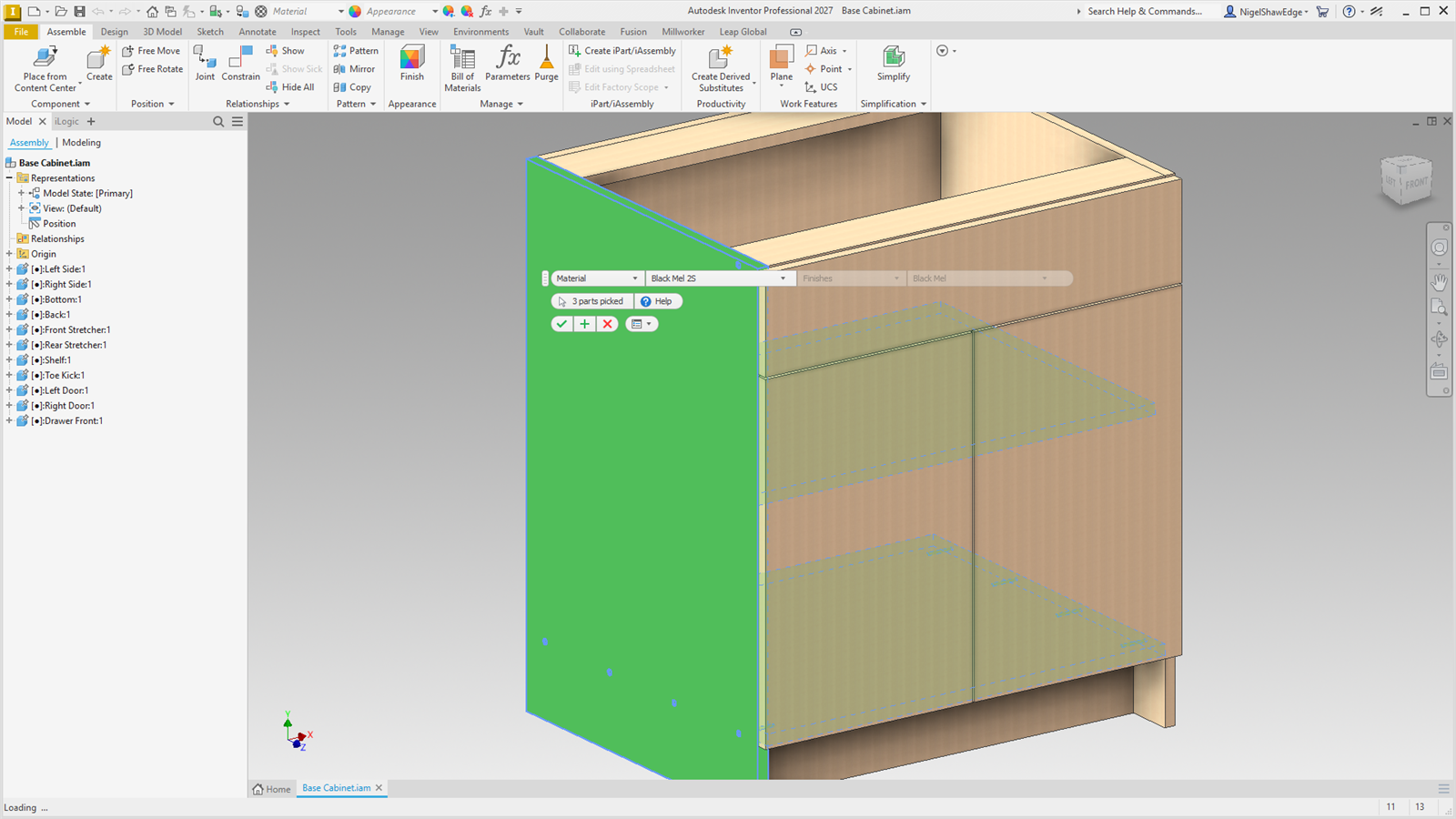
A material works as Assign material does in the manager (with its face finish); a finish goes on the whole part, after its old looks are taken off (banded and veneered faces keep theirs). A veneer goes on both large faces as Face 1 and Face 2 (the panel's grain is marked along the face when it has none); a PLAM goes on both faces as their finish. Each gets the project's code for it from the workbook. Picked parts light up filled in green, every face, so they show in a busy model. The last choice is remembered for the Inventor session. Content Center parts are left out.
 Part Numbers
Number every part in the assembly from project, item, room and a running ID.
- An assembly. Materials panel → Part Numbers, or Project Info → Part numbers tab → Number parts….
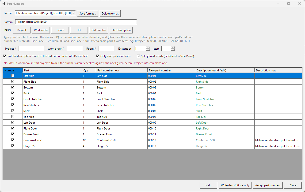
- Fill in the Project, Work order and Room numbers. The project number starts as the one saved on the assembly, else the workbook's (Project Info), else the leading number of the assembly's file name.
- Build the format from those, ID (the running number, from ID starts at by step) and your own text.
:000after a name pads it with zeros. The Work order button puts in{Item}. - Check the grid: each part's number now, the new one, and the description found in its old number. Untick parts to leave them.
- Assign part numbers, then save the assembly and parts.
Example: {Project}{Item:000}.{ID:00} gives 261234001.01 (job 261234, work order 001, then 01, 02…). Save formats by name and choose one from the list. Parts are numbered in browser order; library and Content Center parts are left out.
Descriptions from the old part numbers
Each part's old part number (the one Inventor gave it, usually its file name) is broken into a number and a description: 261055992_SidePanel gives 261055992 and Side Panel; Side Panel_261955.001 gives the same the other way round. Inventor's own names (Part3) give neither. The grid shows the Description found (edit it there before writing) and the Description now.
- Put the description found in the old part number into Description (ticked): Assign part numbers writes it into each numbered part's Description as it gives the new number. Green: it will be written; grey: it won't (hover for why).
- Only empty descriptions (ticked): parts that have a description keep it. Untick to replace them.
- Split joined words: SidePanel becomes Side Panel.
- Write descriptions only writes the descriptions without changing any part number.
- In a format, Old number puts in
{Number}and Old description{Desc}:{Number}.{ID:00}keeps each part's own number with a running number after it.
Never the same number twice
Every number given is logged on the PART NUMBERS sheet of the project's MatFin workbook, with its work order and ID. When you type a work order, ID starts at moves to the next ID after that work order's last one, and the note under the boxes says which that was. A new number that's been given to another part before shows red, and Assign part numbers won't give it: change the ID or the work order. The sheet is read again as the numbers are logged, so a number someone else gave meanwhile is caught too; then nothing is assigned. The workbook is written, so with I use Vault ticked it must be checked out (you can still assign without logging; you're warned). With no workbook in the project folder the numbers aren't checked.
 Cut List
Every panel in the assembly with cut sizes, material, banding, miters and dados, to print or save.
- An assembly of panels, marked and with materials. Materials panel → Cut List.
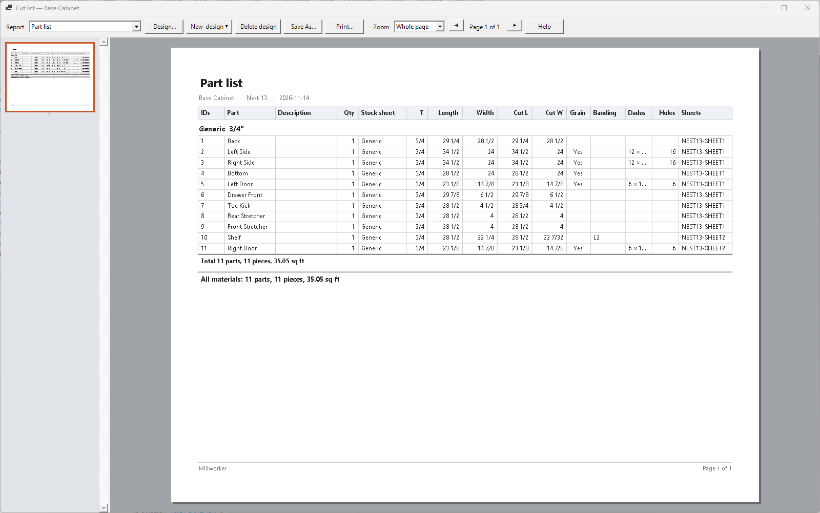
Shows every panel on a Part list design: cut sizes, material, stock, banding, miters and dados, the same as the nest. Save it as PDF or CSV, or print it. Design… changes the columns, title, logo and style.
How a panel is measured
- The largest flat face is the panel face; thickness is measured across it.
- Length runs along the grain edge, or the longest side with no grain marked. Long edges are L1/L2, short edges W1/W2.
- Cut size = finished size less the band thickness on banded edges.
- Hardware (purchased), library and Content Center parts, and parts too thick to be panels (over 2″) are left out.
 BOM
Bill of materials: sheet goods to buy, panels, layups, hardware, finish areas and edgebanding lengths.
- An assembly. Materials panel → BOM.
- A drawing. Tools panel → BOM: the assembly the drawing shows (the active sheet's first view of one).
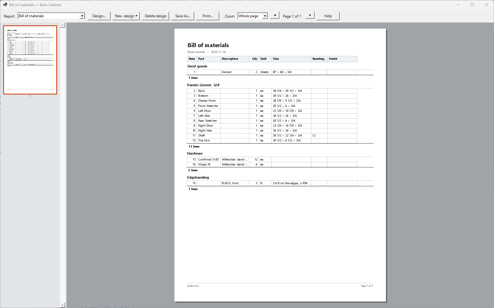
| Sheet goods | The sheets to buy of each stock, from the same planning as the nest, with the total sheets and area under them. |
| Panels | By material and thickness, each with its part number, description and size. |
| Layups | Only when the parts have layups: each layup, its panels and their face area. |
| Hardware | Library, Content Center and bought parts, counted (including the hardware Place Hardware put in). Handles, pulls and knobs (by part number, description or file name) are always hardware, each, never sheets. |
| Edgebanding | Each band's running length, rounded up in feet with 10% for trimming. |
The page is landscape, in six columns: Item, Part, Description (the widest), Qty, Unit and Size. Save it as PDF or CSV, print it, or change the design in Design….
Create Drawing, next to BOM, is not set up yet.
Quick Takeoff
The sheets, layups, hardware and edgebanding to buy, counted from the assembly, as a report.
- An assembly or a drawing of one. Millworker tab → Tools panel → Quick Takeoff (in a drawing, for the assembly the active sheet shows).
The BOM cut down to what you buy: no list of panels, just these groups, in six columns: Item, Code, Description, Qty, Unit and Size. Code is the INNERGY code when there is one (a sheet stock's or its material's, an edgeband's, and for hardware the iProperty set in Settings, References tab: Stock Number unless you change it), else the project's MatFin code (a layup's own code, hardware by its description or part number). The page is landscape and the Description column takes the rest of the width, in the same place in every group, so long descriptions show in full.
| Sheet goods | The sheets of each stock, from the same planning as the nest, with their size and area. |
| Layups | Only when the parts have layups (Tag Layups): each layup's code and description, how many panels and their face area. |
| Hardware | Library, Content Center and bought parts, counted (including the hardware Place Hardware put in). Handles, pulls and knobs (by part number, description or file name) are always hardware, each, never sheets. Its name is the Hardware Library's for the part, else its description; a description that's only a STEP import's header (STEP AP203) gives way to the part number. |
| Edgebanding | Each edgeband's running length over every banded edge, plus 10% for trimming. |
It has a design of its own, Quick takeoff (added to the designs the first time): save it as PDF or CSV, print it, or change it in Design… without changing the BOM's.
 Material Groups
A quick check of the assembly's materials: each material in a colour, its parts lit in that colour while the window is open.
- An assembly. Millworker tab → Tools panel → Material Groups.
A small window beside the model lists every material the assembly's parts use, one row each, with a colour, how many different parts (Parts) and how many are placed (Qty). It opens with every material unticked: tick the ones you want to see and their parts are filled in their colour in the model, so a part with the wrong material stands out. A part's material is the material iProperty when one is set (Millworker Settings), else its Inventor material; parts with none are grouped as (no material). Suppressed parts are left out.
- Show: tick a material to light its parts, untick it to take its colour off; All and None do every row. Refresh keeps your ticks; a new material comes in unticked.
- Colour: click the swatch to choose another colour.
- Select in model (or double-click a row): the picked materials' parts are selected in Inventor.
- Refresh: reads the materials again after you change one, keeping each material's colour.
Close (or Esc) takes the colours and the selection off. Nothing in the model is changed or saved; closing the assembly closes the window too.
 Bodies to Part
Every body in the assembly into one new part, each a separate body with its appearance.
- An assembly. Millworker tab → Tools panel → Bodies to Part.
Inventor's Derive and Simplify make each component one body, so a cabinet base model's panels come in merged. Bodies to Part keeps them apart: a new part with every solid body of every part in the assembly as a body of its own, placed where it is in the assembly.
- Each body keeps its appearance: the component's appearance override if it has one, else the body's own. Faces with their own appearance (edgebands) keep theirs.
- Each body is named after its component and body (Cabinet 1:1 - Left Side).
- Suppressed and hidden components, and hidden bodies, are left out.
The bodies are plain solids, copies not linked to the assembly: changing the assembly doesn't change them. The new part opens unsaved: save it where you want it. One undo in the new part takes them all out.
 Push to MatFin
Set up the project's references in its MatFin workbook: the assembly's materials come in to match to INNERGY, rows are changed, layups made, then one Save.
- An assembly saved in its project folder: Millworker tab → Materials panel → Push to MatFin, between Materials Finishes and Tag Layups.
This is where the project's references are set up: the materials, finishes and layups the reference document (Reference Tables) shows. The Materials panel runs left to right: assign materials and finishes from the Material Manager (that's just the preset), set the project's references here, then put the layups on parts with Tag Layups. INNERGY is used only when Use INNERGY is ticked in Millworker Settings, References tab (with your email and API key); the Vault steps only when I use Vault is ticked there.
- Click Push to MatFin. A workbook that's checked in (read-only) is caught when you save a row: check it out in Vault, then save again.
- The window shows the workbook a tab per group (General notes, Client Ref Mapping, Finishes, Materials, Layups, Hardware…), the workbook's full path above. The assembly's materials come in by themselves: every material (or PLAM), veneer, finish and edgeband its parts use that the workbook hasn't got (by INNERGY SKU, else type and description) is added as a row marked New · from the assembly, with the next free code of its kind. With INNERGY on, one INNERGY has takes INNERGY's name; one it hasn't got is marked Not in INNERGY: look it up. Edit it: the lookup is turned to INNERGY with its name typed in; double-click the match and its SKU and name go on the row.
- See a row: click it. Row info on the right shows it, only the fields its type has (a layup's core and faces spelled out by name), with Edit and Remove row under it. Changing tab clears it.
- Change a row: Edit, on the row (or under Row info), opens it in a window of its own with the fields its type has: sub type (pick from the usual ones or type), EWC code, client code, description, the INNERGY SKU (only with Use INNERGY ticked), and a lookup in the Material Manager or INNERGY. OK keeps the change in the window (nothing goes to Excel yet); Cancel puts it back as it was.
- Add a row: + New row, under the list, opens the same window, empty, for the tab you're on. The next free code of its kind is filled in. OK adds it to the list, marked new.
- Make a layup: on the Layups tab, + New row, then the Core (a material) and Face 1 and Face 2 (finishes): type a code, or press … beside the box (or double-click it) for a window listing them with their code, description, sub type and SKU; search it, then double-click one or press Use it. A finish that isn't in the workbook yet: + New finish… in that window adds it to the list and puts it in the box. OK on the layup keeps it; Cancel drops it (the new finish stays). Then put it on parts with Tag Layups.
- Save, at the bottom right, writes every change to the workbook in one go, one trip through Excel: rows added, changed and removed, and the rows brought in from the assembly. It shows how many are waiting, Save (3). Closing with some waiting asks whether to save them.
- Update part codes gives the assembly's parts this project's codes after the workbook changes. Check the workbook back in to Vault when you're done.
Checks on Save: every row needs a description, every row but a note an EWC code, and no code may be on two rows. An EWC code you type that another row has goes red at once. The workbook is read again as it's written, so a code someone else added meanwhile, or a row they removed, stops the save and nothing is written. Add rows from… copies rows from your template or another project's workbook (it saves your changes first).
There are no tick boxes here: they belong to Reference Tables in a drawing, where they pick the rows the front page's tables show.
 Tag Layups
Put the project's layups on parts with a mini toolbar: choose the layup, click the panels, Apply.
- An assembly saved in its project folder, whose MatFin workbook has layups (made in Push to MatFin, Layups tab).
- Millworker tab → Materials panel → Tag Layups.
A layup is a core and two faces under one EWC code, for example PAN01 = WUD03 + FIN10 + FIN12. Layups are made in Push to MatFin; Tag Layups puts them on parts, and drawings call them out with the Layup callout.
- Click Tag Layups. It reads the project's layups and the mini toolbar comes up, with the layups in a list (code and description; Inventor shortens the one chosen, so it is written out in full beside the list, and the core and faces are spelled out by name on the row under it). Choose None to clear a layup instead.
- Click single panels in the assembly (or drag a window over them) to pick them; click a picked one to take it out. Panels selected before you click Tag Layups start picked.
- Apply puts the layup on all the picked parts (one undo step) and starts a new pick, for the next layup; change the layup in the list between picks. OK applies and finishes; Cancel or Esc stops.
On the part: the custom iProperties MillworkerLayupCode, MillworkerLayupCore, MillworkerLayupFace1, MillworkerLayupFace2 and MillworkerLayupDescription. The core's material and each face go on with it, so there's no second step: the core's Material Manager material (with no finish of its own), Face 1 and Face 2 each their own veneer, finish or PLAM, found in the Material Manager by the workbook row's SKU (INNERGY code), else its description. Face 1 is the face already veneered as Face 1; else, on a door drilled for hinge cups, the face away from the cups (its front); else the face at the part's +X, +Y or +Z side. A code the Material Manager hasn't got is still put on the part, and the status line names it. Grade on the toolbar puts the chosen panel grade on the parts: A1 puts A in MillworkerFace1Grade and 1 in MillworkerFace2Grade (the grades are in Millworker Settings, General tab, Veneer); with it unticked, the faces take their veneers’ own Grade from the Material Manager. Picked panels light up filled in blue. Save the assembly to keep it all. Locked parts (checked in to Vault, or read-only) are left and named.
Hardware
 Insert Fastener
Pick a fastener and a hole: it goes into every matching hole in the assembly, skipping holes that already have one.
- An assembly of panels with holes (made with Place Hole, Confirmat, or plain Inventor holes).
- Your fastener in the Hardware Library.
- Hardware panel → Insert Fastener.
One fastener for all the matching holes, in one go.
- Choose the fastener in the mini toolbar's list (each part with its category's icon). Library… opens the Hardware Library to add one; the list is read again when it closes.
- Click a hole: its round wall, in any panel, in any sub-assembly.
- Every matching hole in the assembly lights up: green to fill, grey already has a fastener. The status bar gives the count.
- Insert. Click another hole for the next set, then Done (or Esc).
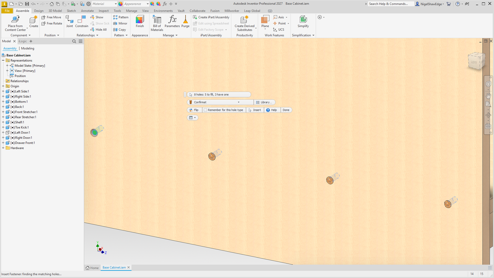
Which holes match
- A hole made with a hole type (Place Hole, Confirmat): every hole of that hole type.
- Any other hole: every hole of the same diameter (within 0.05 mm) and depth (within 0.1 mm), or through like it.
- Patterns and mirrors: when you pattern or mirror a hole made with a hole type (or the Place Hole node itself), every copy counts as that hole type too, so it gets the same fastener.
- Parts made from a base model (Make Components): the holes are read from the base model, so they keep their hole types, patterned copies included.
Holes that already have a fastener
They are skipped, so running it again never doubles up. Hardware Millworker puts in remembers the hole it is in, and any hardware part sitting on a hole's axis counts too. The end message says N inserted, M skipped (already have a fastener).
How the fastener sits
A hole without a hole type that goes right through is filled from its countersunk or counterbored end, the head flush with the face. It goes in as the Hardware Library says: its Direction, Seat offset and Turn, in its model state (or by its MW_Seat iMate when it has one). It is tied to the hole with constraints (its axis to the hole's axis, its origin plane to the panel face), so it follows the panel. When it can't be tied, it is grounded where it was put. The parts go in a Hardware folder in the browser, all as one undo step.
| Flip | The fastener the other way round in the holes. |
| Remember for this hole type | Makes this part the hole type's fastener (Hole Types), so Place Hardware puts it in those holes from now on. Only for holes made with a hole type. |
 Place Hardware
Put the fastener in every tagged hole: the hole type's fastener, or the joint tools' screws, dowels, cams and hinges.
- An assembly of panels whose parts have Millworker hole or joint nodes (for example made with Make Components from the multi-body part).
- Hardware panel → Place Hardware.
The hole and joint tools tag each hole with what goes in it. Place Hardware finds the tags in every panel and puts a part in each hole, in the panel's place in the assembly, in a Hardware folder in the browser. It ends with a count of each.
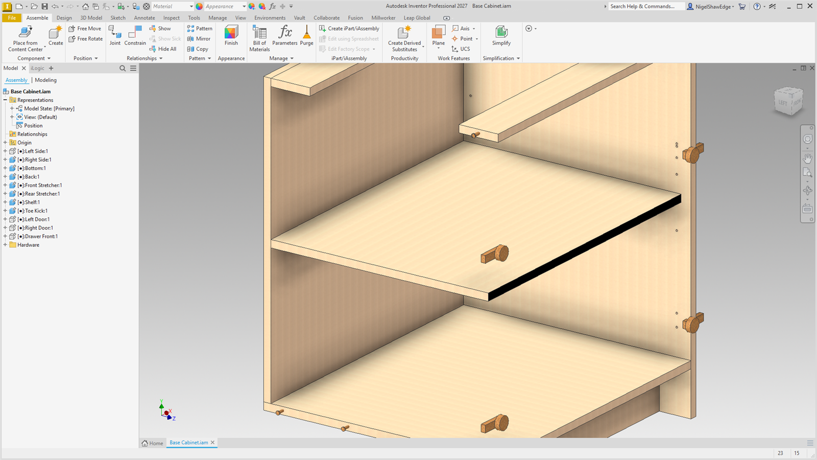
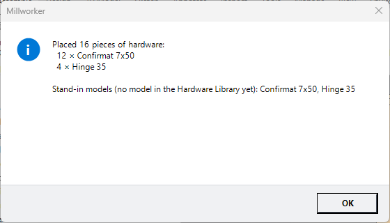
| Holes | What is placed |
|---|---|
| Place Hole, Confirmat | The hole type's fastener (Hole Types). A hole type with no fastener that doesn't need one (shelf pins, a line bore) gets nothing. |
| Dowels | A dowel (8x35) across the joint. |
| Cam Dowels | The cam housing, the cam bolt and the dowels. |
| Domino, Clamex P, Biscuit | The tenon, connector or biscuit, along the joint. |
| Pocket Screws | A screw where the pocket steps down. |
| Hinge Holes | A hinge at each cup's centre on the door. |
Without a fastener of its own, the library's row for the kind and size is used, then its row with a blank size, then a stand-in.
Holes that already have a fastener are skipped: ones filled with Insert Fastener, or a library part you put in yourself. Running it again after changes replaces only its own earlier hardware, as one undo step, so nothing doubles up. A part made by Make Components gets the tags of the bodies it takes, so each piece is placed once.
 Hardware Library
A simple list of your hardware parts: a category, a model state and which way each goes into the hole.
- Fasteners or Hardware panel → Hardware Library (also with nothing open), or Library… in Insert Fastener.
Your hardware parts (screws, Confirmats, dowels, hinges, inserts…), one row each. Hole types say which part goes in which hole; Insert Fastener and Place Hardware put them in.
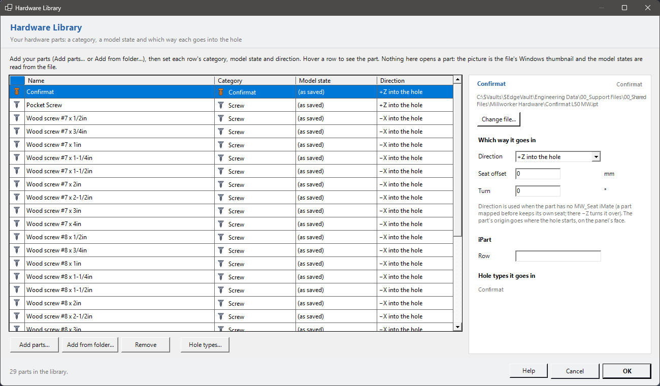
Adding parts
- Add parts…: choose one or more .ipt or .iam files.
- Add from folder…: choose a folder; every part in it is listed to tick, its category guessed from its name (confirmat, dowel, hinge, screw, insert, nut, cam, pin, magnet, lock, handle…).
- Remove takes the selected rows out (the files are not touched).
The list
| Category | Screw, Confirmat, Dowel, Insert/Nut, Hinge, Cam/Connector, Shelf pin, Bolt, Handle, Magnet/Catch or Other. Its icon shows on the row and in the tools' lists. |
| Name | What the tools list. Blank: the file's name. |
| Model state | The model state placed (a cabinet hinge open or closed). (as saved) is the one the file was saved in. The states are read from the file. |
| Direction | Which of the part's own axes points into the hole: +Z, −Z, +X, −X, +Y or −Y. |
Hover a row to see the part. The picture is the file's Windows thumbnail: no part is opened, so nothing asks to resolve a link and nothing can crash.
Selected part
| Direction | As in the list. The part's origin goes where the hole starts, on the panel's face. |
| Seat offset | mm: moves the part along the hole; positive goes further in. |
| Turn | °: turns the part about the hole's axis. |
| iPart row | An iPart factory: the member to place (blank: the default row). |
| Hole types it goes in | The hole types whose fastener this part is. Hole types… opens them. |
A part that already has an MW_Seat iMate is seated by it; there −Z turns it over. An iPart member from another library whose factory is not on this PC (for example one from W4INV) can't be placed by Inventor: Millworker saves a standalone copy beside it (name MW.ipt, the original untouched) and uses that.
Stand-ins
Place Hardware puts a plain purchased part shaped from the hole's sizes in a tagged hole with no part in the library, made once in the Millworker Hardware folder. Its Part Number is the hardware's name, so the BOM counts them and the cut list leaves them out.
OK saves the library in Millworker Hardware.json next to the material database. A library from before keeps working.
Tools
 Parameters side bar
The active document's parameters at a glance in a docked window, with a copy button for each name.
- Tools panel → Parameters. A dockable window, docked right at first. It stays open and follows the active document.
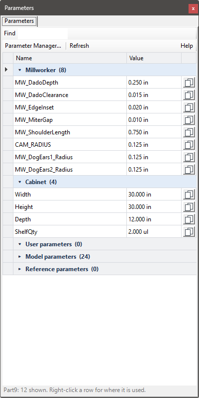
- Name, Value and a copy button that copies the name, to type into a model or a value box.
- Grouped as in the Parameter Manager, with Find at the top.
- Double-click a parameter, right-click → Open in the Parameter Manager, or Parameter Manager… at the top for everything else.
iProperties tab
In assemblies there is an iProperties tab beside Parameters. It shows the iProperties of what is selected: nothing selected, the assembly; a subassembly, that subassembly; a part (or a face or edge of it), that part.
- Every category has its own group (click to fold): Summary, Document Summary, Project, Custom and others.
- Type a value and it goes on that document at once, as one undo step, in the property's own kind (date, number, Yes/No, text). A value that does not fit is refused, with why on the status line.
- The last row of Custom adds a custom iProperty (name, then Tab to its value).
- Buttons: Part priority, Pick a part (one click, inside subassemblies too), Top assembly, Refresh and Find.
Save the assembly to keep the changes in the files.
 Parameter Manager
Every parameter with every column, groups, lists, tolerances, checking as you type, and more.
- Tools panel → Parameter Manager, or from the side bar. A window of its own that floats beside the model and stays open.
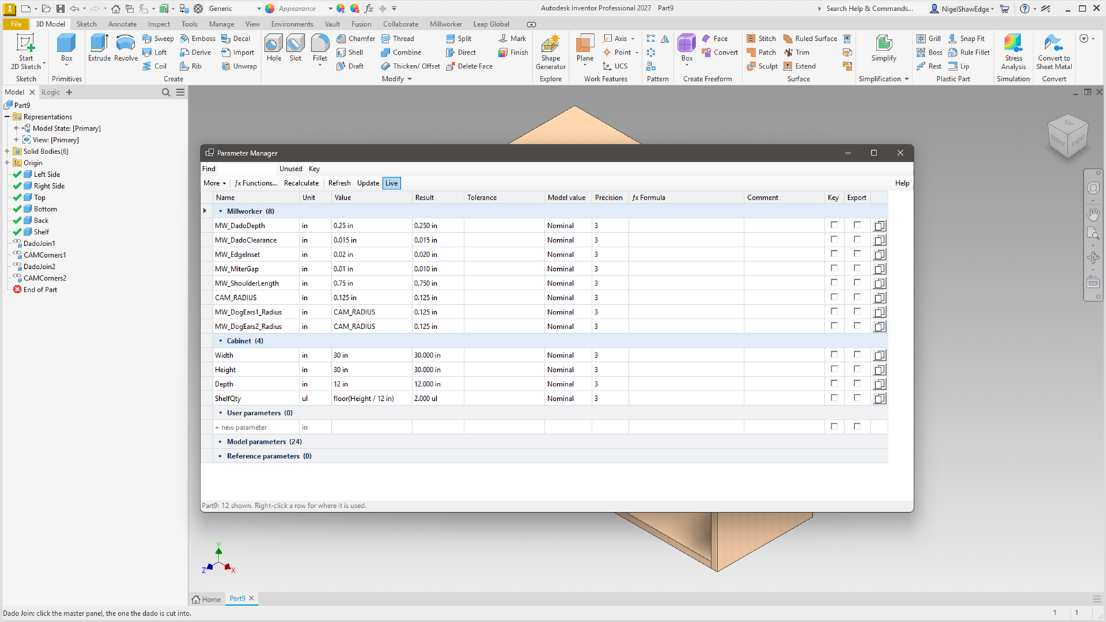
Columns
Name, Unit, Value (its expression; a list parameter's is a drop-down), Result, Tolerance, Model value (Nominal, Upper, Lower or Median), Precision, ƒx Formula, Comment, Key, Export and the copy button. The name stays in view as the columns scroll.
Checking as you type
A name, value, formula or tolerance that will not do turns red as it is typed, the reason shows on the status line, and it cannot be finished (Tab and Enter wait; Esc puts it back). Names follow Inventor's rules.
Groups
Each custom group (Millworker's among them) has its own header row, then the user parameters in no group, the model parameters and the reference parameters (these two start folded). Click a header to fold it. Drag rows by their left edge onto another group to move them, or within a group to reorder them.
New parameter in one row
The last row of User parameters ("+ new parameter"): type the name, Tab to Unit, Tab to Value.
Keyboard
Cells edit as you reach them; Tab goes Name → Unit → Value. In Unit, an arrow key opens the list and Enter picks.
Right-click and More
- Where used lists what a parameter drives (and what drives it); click one to select it in the model.
- Make a list… / Edit list…: one value per line; Not a list makes it plain again.
- Copy name, Move to group, Delete.
- More: Set value (
{x}is each one's own), Scale or Offset several at once; new, rename and delete groups; fold all; delete unused user parameters; export and import as CSV.
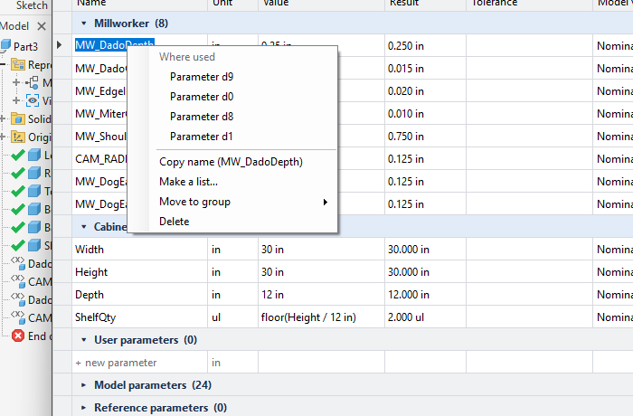
Undo and updating
Each change is one undo step. Live updates the model after each change; turn it off and use Update for several changes.
Functions and formulas
IF/THEN formulas and your own functions on parameters, worked out by Millworker.
- Parameter Manager → the ƒx Formula column, and ƒx Functions….
Formulas
A formula can do what Inventor's expressions cannot:
| Conditions | IF Width > 30 THEN 3 ELSE 2, ELSE IF chains, if(Width < 25, 1, 2) |
| Comparisons and logic | = <> < <= > >=, AND OR NOT |
| Arithmetic | + - * / ^ % |
| Functions | min max abs round (round(x, 2)) floor ceil sqrt sin cos tan (degrees) pow sign clamp |
| Names | The document's parameters and your own functions. |
Lengths are in the document's length unit and angles in degrees: Width is 30 in a 30″ part. A number can carry its own unit (254 mm). The parameter's value becomes the result and is worked out again a moment after any change to the document (one undo step; Recalculate does it now).
The value cell of a formula parameter is pale yellow. A formula that cannot be worked out is red, with why on its tip. The formula is kept on the parameter, so it stays with the document.
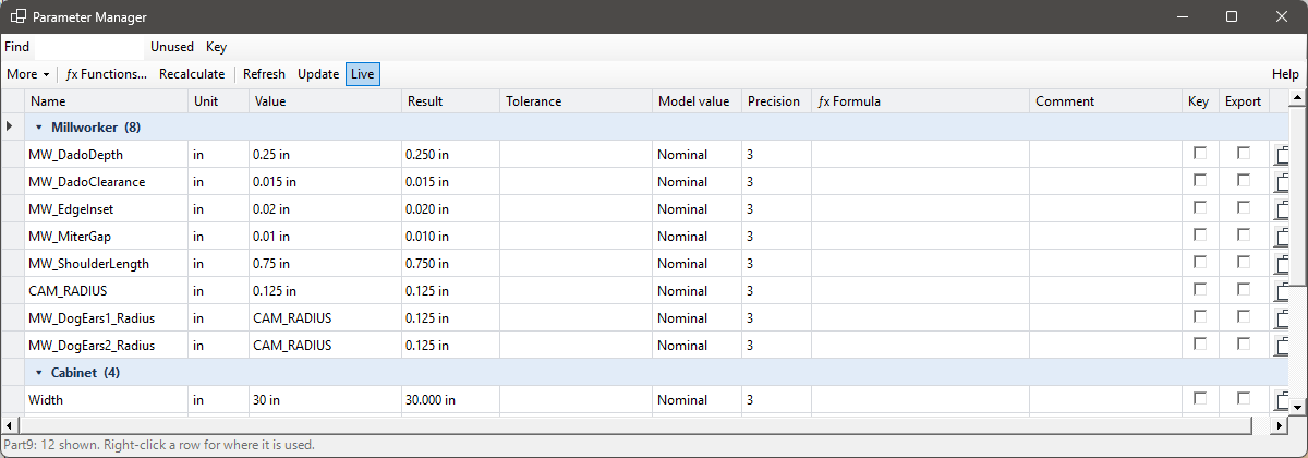
Your own functions
ƒx Functions… lists your functions, one row each: Name, Arguments, Formula and Description.
Example: ShelfCount (h) = IF h > 30 THEN 3 ELSE IF h > 20 THEN 2 ELSE 1, then the formula ShelfCount(Height).
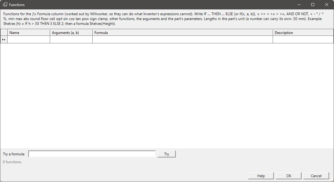
- A function can use other functions, its arguments and the document's parameters (not itself).
- A row that will not do is red, and OK waits until it is put right.
- Try a formula works one out on the active document.
- Functions are kept in
Millworker Functions.jsonnext to the material database, and each document copies in the ones its formulas use, so it still works on a PC without them.
 Create
Make a new drawing, part, base model, assembly, cabinet, curved panel or sheet metal part in its project and work order folder, with the project's info on it.
- With nothing open: Millworker tab → Create panel → Create.
- In a part, assembly or drawing: Millworker tab → Tools panel → Create.
A new file in the right place, in two steps. Every project is a folder in the projects root (Vault's working folder, Engineering Data), and its work orders are folders in it.
- What to make. Pick Drawing, Part, Base model, Assembly, Cabinet, Curved panel or Sheet metal. Beside it you see what it's for, the template it starts from, and a picture of it. Next (or double-click the kind).
- Where it goes. On the left, the project folders (newest first; type to search). The project of the file you have open is picked to start with.
- An existing project: its work order folders are listed, and its project info is read from its MatFin workbook's PROJECT_INFO tab. Change anything and Create saves it back there.
- + New project…: fill in the project info. The project number and name name its folder (Settings, Create tab: {Number} - {Name}), and a MatFin workbook is made in it from the template with this info.
- Create makes the folders, the MatFin when the project has none, saves the project info, then makes the file from its template, saves it there and opens it. The file carries the project as custom iProperties (Project Number, Project Name, Project Manager…), the work order (Work Order Number, Work Order Name, and Item Number for Part Numbers) and Inventor's own Project. With I use Vault ticked, it reminds you to check the new folders and files in.
Templates (Settings, Create tab): one for each kind. Blank: Inventor's own (a drawing: the drawing template on the Sheets tab; sheet metal: Inventor's sheet metal template). In Inventor 2027, a copy named <name> - 2027 beside a template is used when there is one, so 2026 templates aren't migrated. The same tab sets the projects root and how new project, work order and file names are made.
 Project Info
The project's details and part numbers in its MatFin workbook, and the iProperties pushed down to every subassembly and part.
- A part, assembly or drawing. Millworker tab → Tools panel (the second panel, next to Settings) → Project Info, the first button.
One window for the job, in three tabs. The project's details and its part numbers are kept in the project's MatFin workbook (the one Reference Tables and Push to MatFin use), on two sheets of their own beside MATFIN, so everyone on the job sees the same ones. The workbook's path is shown at the top; with no workbook in the project folder, Make the MatFin workbook starts one as a copy of the template (an unsaved drawing finds the workbook through the models it shows).
Project
Project number, Project name, Project manager, Customer, Site address and Project info (notes, several lines). They load from the project's MatFin when Project Info opens; Load from workbook reads it again, or, for a file not saved in its project folder yet (a new assembly), lets you pick the MatFin and loads its PROJECT_INFO into the fields. Save to workbook writes them on the workbook's PROJECT sheet (a field in column A, its value in B). A field you add on that sheet yourself shows here too. The buttons along the bottom work from every tab: Save to workbook keeps the Project tab's fields in the MatFin; Set on this file puts them, and your iProperties list, on the open part, assembly or drawing as custom iProperties (Project Number, Project Name, Project Manager…) for title blocks and parts lists; Push down does the same on the open file and every subassembly and part in it. When the workbook has no value yet, the box starts with the assembly's own iProperty (and the job number for the project number). With I use Vault ticked in Settings, a checked-in workbook has to be checked out first.
One workbook: the PROJECT_INFO and PART NUMBERS tabs are added to the project's MatFin workbook, beside MATFIN; there is never a second file. Make the MatFin workbook shows only when the project folder has none, and makes it as a copy of the template. When Project Info opens a workbook whose PROJECT_INFO tab is missing or empty, the tab is set up there and then with the fields listed, ready to fill in and save (a checked-in workbook: when you save, once it is checked out). PART NUMBERS is added the first time a number is given. The tabs come from MatFinInfoTemplate.xlsx in C:\ProgramData\Autodesk\ApplicationPlugins\Shaw Dev\Templates when it has one: its sheets named PROJECT_INFO (or PROJECT) and PART NUMBERS are copied as they are, title rows, formatting and all; an empty PROJECT_INFO gets FIELD and VALUE headings. A new MatFin workbook starts from the same template (its general notes) when no template workbook is set in Settings, References tab. On the project tab the fields are under a heading FIELD with VALUE beside it; on PART NUMBERS the headings are WORK ORDER, ID, PART NUMBER, PART, ASSEMBLY, DATE and BY, in any order and in the first ten rows (a heading left out is just not filled). Without the template the tabs are made plain.
Part numbers
Every part number given in the project, from the workbook's PART NUMBERS sheet (work order, ID, part number, part, assembly, date, who). The top list has one line per work order: how many numbers it has and the last ID; click one to see its numbers below. Number parts… (in an assembly) opens Part Numbers, which carries on from the work order's last ID and won't give a number that's been given to another part.
iProperties
The iProperties every file in a job should carry (project, customer, room, designer, your own). Type them once on the top assembly and push them down.
- Choose the fields in Millworker Settings, Project info tab (or Fields… in the form). Each row is a field: its name in the form, the iProperty it fills, Choices to pick from (separated by
;, blank for a plain box), and whether it goes to Subassemblies and Parts. The iProperty can be one of Inventor's own (Project, Designer, Description, Title, Company …; the box suggests them, and Category shows where it is) or any other name, which is a custom iProperty. ▲/▼ set the order. - Open Project Info, iProperties tab. The fields are shown in that order with the top assembly's values. Tab (or Enter) goes from one to the next; on the last, Enter goes to Push down. Beside each field is its category, and (new) when the assembly doesn't have it yet.
- Push down puts the values on the file and on every subassembly and part in it, as each field is set to go (in a drawing: the drawing and the models it shows, and their parts; a part has nothing below it). An iProperty that isn't there is made (in Custom). Blank fields are left alone, unless Push blank fields too is ticked (then they clear the value below). Set on this file writes the open file only.
It's one undo step. Save the assembly to keep the values in the files. Only values that differ are written, so unchanged files aren't touched.
Left out: library, Content Center and iPart/iAssembly member files, and read-only files (checked in to Vault). The read-only ones are named under the fields: check them out and push again.
 Design Copy
A new, renamed version of an assembly (or a drawing and its assembly) with everything it uses, in another folder: Copy or Reuse each file, rename them all at once from the ribbon, set iProperties.
- In an assembly or a drawing: Millworker tab → Tools panel → Design Copy. The window opens and reads that assembly or drawing in.
- With nothing open: Millworker tab → Create panel → Design Copy. The window opens empty: Open the assembly (.iam) or drawing (.idw, or an Inventor .dwg), or drop it on the window.

A new version of an assembly, the way Inventor's Copy Design and Pack and Go do it, with the renaming done in batches. Every file it uses is a row: subassemblies, parts, the base models of derived parts, the drawing and its models, linked files. The originals aren't changed: they're copied as they are on disk, and only the copies are opened, repointed and saved. A cover shows while files are read or copied. To rename the files themselves, or only save new iProperties, with no copy, switch Rename on (below).
The workflow
- Open the assembly or drawing (it's read for you when you start Design Copy in one). Add files… brings in files that go with it: another assembly, a part it doesn't use yet, a PDF or spreadsheet; each comes in at the top of the tree with everything it uses. Find related… looks in the design's own folders (not library or Content Center ones) for files the design doesn't use: other drawings, assemblies, parts, presentations, spreadsheets and PDFs. They come up in a tree, each with what it uses (a drawing with its assembly, the assembly with its parts; files already in the list are greyed). Tick the ones to add: ticking a drawing or an assembly ticks what is in it, and a part you untick under it comes in reused (its copies point at the original). Tick the drawings ticks every drawing at once. This check also runs by itself right after a design opens when there are such files; untick Look for these each time a design opens to stop that (Find related… still works). You can drop files on the window too.
- Copy to: From shows the file being copied; under it, To: type the folder the copies go to, or click the folder icon in the box. Every row going there follows when you change it; a folder typed on a row stays. A note under the box warns when the folder is in the Vault working folder (nothing is checked in) or outside the Inventor project. The tick boxes under them, side by side, with any warning beside them: Keep subfolders (a file from a subfolder of the source's folder goes in the same subfolder there), Open when done (Copy only: opens the new copy's top, the drawing when you copied a drawing, else the assembly).
- To project… (Copy to) copies the design into another project in one step. Pick the project (the folders under the projects root in Millworker Settings, as Create lists them; type to find one) and its work order, the project folder itself, or a New work order… (its folder is made when the copy is made). Copy to is set to that folder. Change 261097 to 261100 puts the new project number in every new file name and iProperty that carries the old one; a reused file that carries it is copied so it can take it (library and Content Center files stay reused). The MatFin workbook: link the copies to the project's own (Use existing), copy it into the project folder as
<job>_MatFin.xlsxwhen the project has none, or keep linking to the source project's. Undo takes it all back. - Copy, Reuse or Exclude each file: click the icon at the start of its row; each click goes Copy, Reuse, Exclude; when a Copy row's file is already in the destination (it shows red), the click from Copy goes to Use existing first. Use existing (teal link) copies nothing: the copies point at the file already in the destination folder (from an earlier copy, say), under its new name or, when that isn't there, its own name; a linked file such as the MatFin workbook takes the one file of its kind there (261100_MatFin.xlsx for 261097_MatFin.xlsx). That file is left as it is, iProperties too: the row (and the iProperties panel) shows that file's values, greyed, not the original's. You can change its name or folder to point at another file there. Reuse is different: the copies keep pointing at the original in the source folder. A file set to Copy whose name is already in the destination shows red; right-click and pick Use existing for every file already in the destination to set them all at once.Exclude (red circle) leaves the file out of the new design: it isn't copied, and it is taken out of the copied assemblies that use it (an excluded subassembly takes what is only in it out too). A file a copied derived part or drawing needs can't be excluded: it shows red. Copy (green) makes a new file; Reuse (blue) keeps pointing at the original. With several cells selected down the table, the click sets all their rows; right-click rows for Copy and Reuse too. Set on a subassembly or a model, its whole contents go the same way (library, Content Center and linked files stay reused unless you set them yourself).
- Rename in batches: click a column's heading to select the whole column (Ctrl+click for more columns, or drag over cells for some of them), then right-click it for the tools (below). Or type in a cell; Ctrl+V pastes a column of names from Excel down the rows.
- Fix anything red (the Notes column says why), then Copy design. It asks once, then makes the copies and, when Open when done is ticked, opens the new top: the drawing if you copied a drawing, else the assembly. Nothing else is opened.
Rest the mouse on a row to see the file's picture, its type and what its copy will be.
Tools for the selected cells (right-click)
Right-click a column heading or the selected cells for these. Every tool works on the cells selected: a whole column when you clicked its heading. Most open a small window with their settings and a preview of every value that changes; OK makes the change, Undo (Ctrl+Z) takes it back. Only files set to Copy change.
| Auto name | Each value made from a pattern: {Top} the top assembly's new name, {N:00} a running number, {Original} the old name, {Name} the new name now, {Number} and {Desc} the number and description in the old name (261234_Side Panel → 261234, Side Panel), {Kind}, and any iProperty, e.g. {Top}-{N:00} or {Number}_{Desc}. Insert puts them in. |
| Find and replace | Text found in the selected cells and replaced; an empty Replace takes it out. Match case when it matters. With nothing selected it looks in every name and iProperty cell. |
| Prefix / suffix | Text in front of, or after, each value. |
| Number | A running number down the column, before or after the value or instead of it. Type the first number as it should look, any length: 261085001 counts 261085001, 261085002…; 001 counts 001, 002…; 26195683854322001 works too. Step is how much it goes up by. |
| Copy to column | The selected cells' values copied into another column on the same rows: New file name into Part Number, Part Number into Description, File name (the old name) into New file name… |
| Split part number | The selected cells' values (select the File name column for the old file names) broken into their number and description, 261234_SidePanel into 261234 and Side Panel, each into the column you choose, as Part Numbers does. Its preview shows one row per component: the value now, the new part number and the new description. |
| Change case | CamelCase (the default: lower back panel → LowerBackPanel, each word's first letter capital and the spaces taken out), UPPER, lower, Title, or just the spaces tidied. |
| Back to original, Clear | (Edit) The selected cells back to the original file's values, or emptied (iProperty cells). |
Columns
- Right-click a column heading, or inside the selected column: Copy <column> to lists the table's other columns; pick one and the values are copied into it row by row. Fill from copies another column into this one, Reset the column puts it back to the original values, and the tools above work on it too. Below them are the files' own: Copy, Reuse, back to the original.
- Ctrl+C copies the selected cells (one line per file); select another column and Ctrl+V pastes them in, row by row. One line pastes into every selected cell; lines from Excel paste down the column.
- Material shows each part's material (the Millworker material from the Material Manager, else Inventor's). Double-click a part's cell, or select parts and right-click Set material…, to give the copies another: the picker lists the Material Manager's materials (type to find one; Material Manager… opens it to add or change one). A new material shows bold, like any edit (hover: what the part has now). The copy gets it as Materials & Finishes puts it on: the material, its look, its finish on the large faces and its codes. Back to the part's own material undoes it; Reuse rows and library parts keep theirs. Material (Columns) shows or hides the column.
- Highlight repeats in <column> (right-click the heading, ticked when on): any value another file in the table has too is shown red with white bold text, so two files don't end up with the same name or part number (Vault won't take that). New file name compares the whole name with its extension (Cabinet.iam and Cabinet.idw are different files); an iProperty compares the models with each other and the drawings with each other, as a drawing usually carries its model's part number. Reused files count with their own values; excluded files don't count. It stays on for that column next time.
- Columns… (View, or right-click a heading) lists every column side by side: Design Copy's own, then the iProperties in Summary, Document Summary, Project and Custom. Tick the ones to show; kept for next time. Action, File name, New file name and Notes are always shown (greyed). Type a name under Custom for one no file has yet. A version problem still shows in Notes when Version is hidden.
- Text size (View) makes the table's text bigger or smaller, 8 to 16 pt; the rows grow with it.
- Action, Type and File name stay at the left when the table scrolls right; you can still size them.
- Drag a heading to move the column (a blue line shows where it goes); a click on a heading still selects the column. Set the columns once: their order and widths are kept as you change them, and the table opens the same next time. Reset order puts them back.
- The iProperty columns start as Part Number, Description and Stock Number. Tick others in Columns…, or right-click a heading for Add iProperty column…; untick one (or right-click its heading) to take it out.
- Edited cells are bold, in blue on a pale blue tint (hover: what it was). A reused row shows the original's values, greyed.
- Part Number follows the new name when it was the file name, as in Copy Design, until you change it.
The table
- Esc stops only what you are doing: a cell being typed in goes back to what it was, a column drag or sizing stops, the hover picture goes, a folder being typed goes back, else the selection is cleared. It never closes the window: Cancel, the close box or Copy design do that. In a small pop-up (Find and replace, Number…) Esc cancels that pop-up.
- Tree (View) shows the files as the assembly is built: a subassembly's files indented under it; click ▸ to close or open it (Expand all, Collapse all). A file used in several places shows under each, and is one file: change it anywhere and it changes everywhere. Select one of its rows and its other rows are tinted too. Flat lists every file once.
- Base models once (View, on): each base model shows as one row under the top level (after its other files) instead of under every part made from it. Nothing about the links changes: the derived parts still point at it, and Copy, Reuse and renaming work on that one row.
- Right-click rows: Copy, Reuse, Use existing, Exclude, back to the original name and values, take an added file off the list, open the original's folder.
- A picture a file uses that isn't there (a library part's image) is left out of the list: there is nothing to copy or point at.
Copy, Rename or Update
Three choices in the Design group say what Design Copy does. It remembers the last one you used.
- Copy: new files go to the Copy to folder, and the originals aren't changed. The button reads Copy design.
- Rename: nothing is copied. The files themselves are renamed and saved where they are. The Destination column is hidden, the Copy to folder is greyed, and the button reads Rename design.
- Update: nothing is renamed or copied. Change the iProperty cells (by hand or with the ribbon's tools), then click Update iProperties. Only the files whose iProperties changed are opened and saved, with the names and folders they have. The New file name and Destination columns are hidden. The action icon reads Update or Keep.
Rename and Update work the same way below: the files are closed in Inventor first and nothing is opened after, and read-only (Vault) files and unsaved changes stop them.
- Fixing a wrong job number: say everything was named 1097 and should be 1095. Choose Rename and open the assembly (or its drawing), then use New name and type 1095…. Every file that has 1097 gets 1095: the drawings, subassemblies, parts, base models, their Part Numbers and other iProperties. Then click Rename design. Each file is saved under its new name in its own folder, and everything in the list that uses it is pointed at the new name. When all of that has worked, the old 1097 files go to the Recycle Bin.
- In Rename, the action icon reads Rename (rename it, or save it with the same name for its iProperties) or Keep (leave it as it is). Exclude isn't offered in Rename or Update, because nothing is taken out.
- When Rename is chosen, or a design is opened with Rename chosen, the drawing beside each model that has its name is added for you, so the drawings follow the new names. Add any other drawing that uses these files with Add files. A file that isn't in the list isn't changed, and it would lose a renamed file.
- The files are closed in Inventor first; nothing is opened when it's done (open the new names yourself). A window open on a file that isn't in the list but uses them stops the rename until you close it, and so do changes that aren't saved.
- Shown red, and so stopped: a read-only file (checked in to Vault), which you check out first or rename in Vault; and a renamed file used by a file set to Keep, which would lose it.
- If anything doesn't work, nothing goes to the Recycle Bin: both the old and the new files stay in their folders, and the message lists what failed.
New name
New name (Design) gives the whole design its new name in one go, from the top: the drawing when you opened a drawing, else the assembly. Type the new name, and the part that changed is picked out, widened to the whole piece between separators: 261085001_QuarryTrails… to 261089001_QuarryTrails… changes 261085001 to 261089001.
- The same change in every file that has it (on): every file's new file name and iProperties that carry 261085001 get 261089001: the drawing, subassemblies, parts, base models, spreadsheets and other linked files. A reused file that carries it is set to Copy so it is renamed too (library and Content Center files stay reused). The preview lists every change.
- Only the drawing and its assembly are new (or only the assembly): everything else is reused, so the new top points at the same parts.
The iProperties panel
On the right, every iProperty of the file selected (one row, or a cell on it), grouped as Inventor groups them; with nothing selected, or a whole column, the top assembly; a drawing's row shows the drawing's. Bold values are what the copy will get from the table (hover: what the original has). It only shows: nothing is written to the original. Right-click a property to add it to the table as a column. Drag its edge to make it wider; the width is kept.
Inventor versions
The Version column shows the Inventor each file was saved in (2026, 2027…). Inventor can't open a file saved in a newer Inventor, and a file it saves is moved up to its own version, which the older Inventor then can't open.
- Newer than this Inventor (red, or noted on a reused row): Inventor 2026 can't open a 2027 file. It can only be reused, and Opening or adding one says so plainly ("saved in Inventor 2027: open it in Inventor 2027 instead"). The status line counts them.
- Older, and its copy will be saved (amber): a 2026 file copied in Inventor 2027 that gets pointed at other copies or new iProperties is saved by 2027, so Inventor 2026 won't open the copy. Copy design says how many before it starts. A copy that is only copied (nothing changed in it) stays in its own version. To keep a design in 2026, run Design Copy in Inventor 2026.
Read-only files (Vault)
A file that is read-only on disk and isn't a library or Content Center file is checked in to Vault. Its row is greyed and its note says so, and the status line counts them. The copy can still be made (the copy is writable), but from the local file as it is, which may not be Vault's latest. To copy the latest: check it out (or Get the latest version) in Vault, then close Design Copy and open it again so it reads the files afresh.
Checked before the copy
- Red, stops the copy: no name or folder, characters a file name can't have, a name Windows keeps (CON, PRN…), a path over 259 characters, two copies with the same name in the same folder, a file of that name already in the folder, or the original's own path.
- Amber, asked about: a copy keeping the original's name (Inventor works best when every file's name is its own), a copy nothing copied uses (every file that uses it is reused), a file with changes not saved (the copy is made from the file as last saved: save first).
How the copy is made
Each Copy file is copied to its new name (a read-only flag from Vault is taken off the copy). Then, children first, each copy that uses a copied file, or gets new iProperties, is opened unseen: its references are pointed at the copies (assembly to its parts and subassemblies, derived part to its base model, drawing to its models, a linked file to its copy), it's brought up to date, the iProperties written, and that file alone saved. Reused files keep pointing at the originals. If it stops part way, it offers to delete the files it made. Nothing is checked in to Vault.
Reference
Troubleshooting
Common problems and what to send with a support request.
| Problem | What to do |
|---|---|
| No Millworker tab | Open a part or assembly (there is no tab in drawings). Check Tools → Add-Ins: Millworker Loaded and Load Automatically. Millworker needs Inventor 2026 or 2027. |
| A panel can't be marked | The part is locked: check it out of Vault, or it is read-only or a library part. |
| Holes didn't follow a resize | Nodes made with early versions may not be dimensioned to the panel: double-click the node and click OK to remake it. |
| No hardware placed | The fastener nodes were made before hardware tagging: double-click each and OK to tag it. Or use Insert Fastener, which finds holes by their size. |
| Materials missing on another PC | Point every PC's material database to the same shared folder. |
| Tool won't take an icon | The control shows its text alone; it still works. |
Support
Send C:\ProgramData\Autodesk\ApplicationPlugins\Shaw Dev\Data\Millworker\error.log, your Inventor version and the steps to repeat the problem to [support email].
Drawings
 Callouts
Click an edge in a view: a boxed note with its material, finish, coating, edgeband or veneer code, left or right of the view, that follows the part.
- A drawing with views of Millworker parts or assemblies.
- Callouts panel → Material, Finish, Coating, Edgeband or Veneer.
Click a line of a part in a view. A boxed note with the code goes just outside the view: left or right of it (the nearer side), level with your click, or, when the line you click is horizontal, above or below it (the nearer), in line with your click; and its leader goes to the line where you clicked. Before you click, the status bar says what the line under the pointer would note (or why there is nothing), and a line with nothing to note doesn't light up. Keep clicking for more; Esc finishes. How far out the note sits is Callout distance from the view in Millworker Settings.
| Button | What it notes |
|---|---|
| Material | The project's code for the part's material: the row in the project's MatFin workbook with the material's INNERGY code as its SKU, else the Material Manager's Default code. A material with neither is not noted (the status bar says so). |
| Finish | Two rows, Face 1 over Face 2: the project's code for the finish on the part (from the Finishes tab, or a tab you added): its MatFin row by INNERGY code, else its Default code. The finish put on its face, else its material's face finish. |
| Coating | Two rows, Face 1 over Face 2: the project's code for the coating on the part (from the Coatings tab), as for finishes. |
| Edgeband | The Edgeband code of the band on a face of the edge you click. |
| Veneer | Two rows: the Face 1 code of the veneer on the panel's Face 1 over the Face 2 code of the one on Face 2 (VEN-01 over VEN-02; a veneer on both faces gives its two codes). A face with no veneer of its own shows the other's. |
| Layup | The layup code put on the part in the assembly (Tag Layups). |
The codes are set in the Material Manager and go onto the parts as custom iProperties when you assign: MillworkerMaterialCode, MillworkerFinishFace1Code, MillworkerFinishFace2Code, MillworkerCoatingFace1Code, MillworkerCoatingFace2Code, MillworkerEdgebandCode, MillworkerVeneerFace1Code and MillworkerVeneerFace2Code. The note shows the iProperty itself (linked text), so when the part is given another material or finish the callout changes with it. A part that has no such iProperty yet (assigned before), or whose iProperty holds a different code (a panel with two edgebands, say), gets the code as plain text, looked up in the Material Manager by name. When there is no code, the name is noted; when the edge has nothing to note, the status bar says so and you can click another edge.
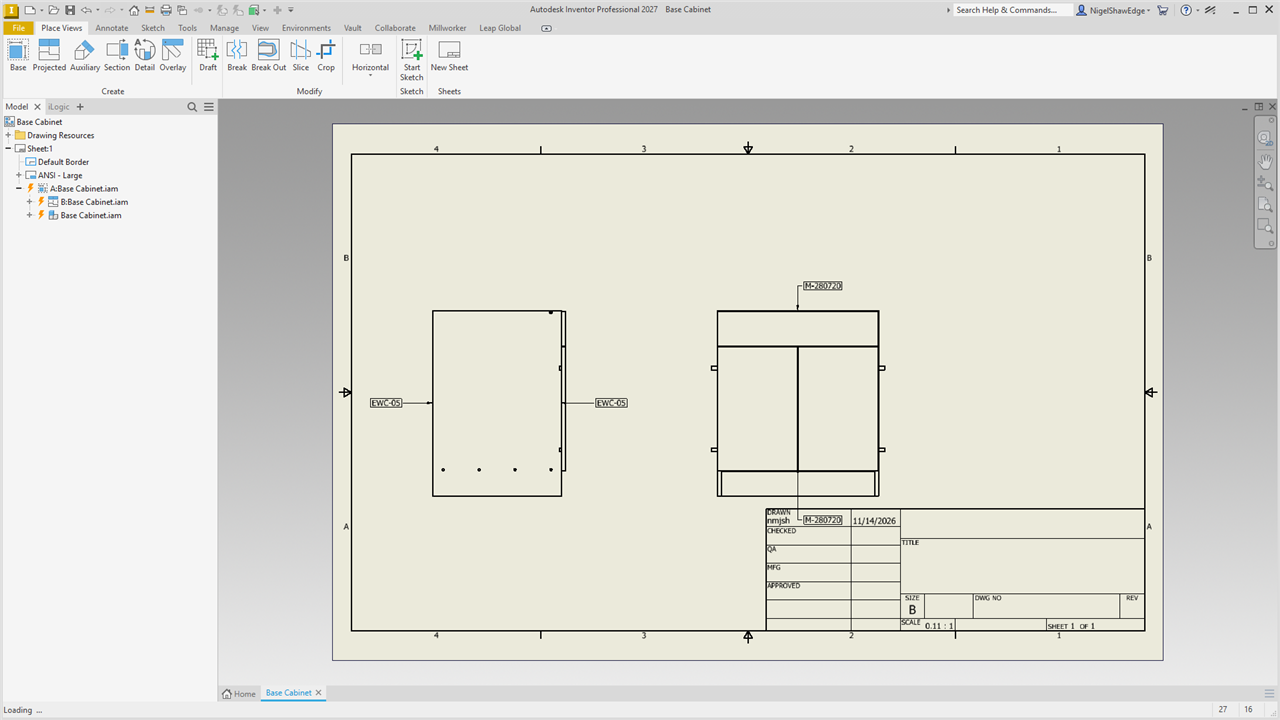
 Align lines and reference boxes
Red dashed lines to line leaders and text up on, and boxes round views, on a layer that never prints.
- Any drawing.
- Align panel → Vertical Line, Horizontal Line or Reference Box.
Vertical Line and Horizontal Line: a line the full height (or width) of the sheet follows the pointer; click to place it, and again for more. Line your leaders and notes up on it. Each is a sketched symbol (Millworker Align Line, made in the drawing the first time), so it can be moved, copied or deleted like any symbol.
Remove Reference Lines: deletes every align line and reference box in the drawing, on every sheet, in one undo step.
Reference Box: click views. Each gets a box round it, the margin out from the view, drawn in a sketch of the view (Millworker Reference), so it moves with the view. Click a view again to fit its box to it after the view has changed.
All of them go on the no-print layer named in Millworker Settings. The first time, the layer is made in the drawing (red, dashed); it is always set not to plot, so the lines and boxes show on screen but never print. To use a layer of your own, put it in your drawing template and give its name in Settings.
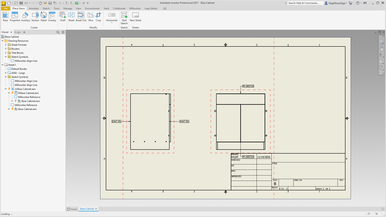
 Section Line
A section view with architectural heads and tails: a bubble with the section and sheet, and an arrow the way it looks.
- A drawing with a view to cut.
- Submittal panel → Section Line.
- Click the view to cut.
- Click the cut point to point, at any angle, as many segments as you need.
- Right-click → Continue.
- Move the section view to where you want it and click to place it.
Section Line runs Inventor's own Section command, so it works the same way:
When the command ends, Millworker puts a head on the end of the cut (a bubble with a solid arrow the way the section looks, and inside it the section's name above a line and the sheet number below) and a tail on its start (a short leg and arrow). They are turned to the cut's angle (the bubble's text stays upright) and tied to the section line, so they follow it when you edit the line.
The section line gets the Millworker Annotation view annotation style as its own override (other sections keep theirs), its letters are cleared, and the section view's label is moved to the bottom left of the view.
The symbols are Millworker Section Head, Millworker Section Label (the bubble's text) and Millworker Section Tail, made in the drawing the first time and drawn pointing right. Put symbols of those names in your drawing template to use your own design; theirs are used as they are. The bubble size is set in Settings.
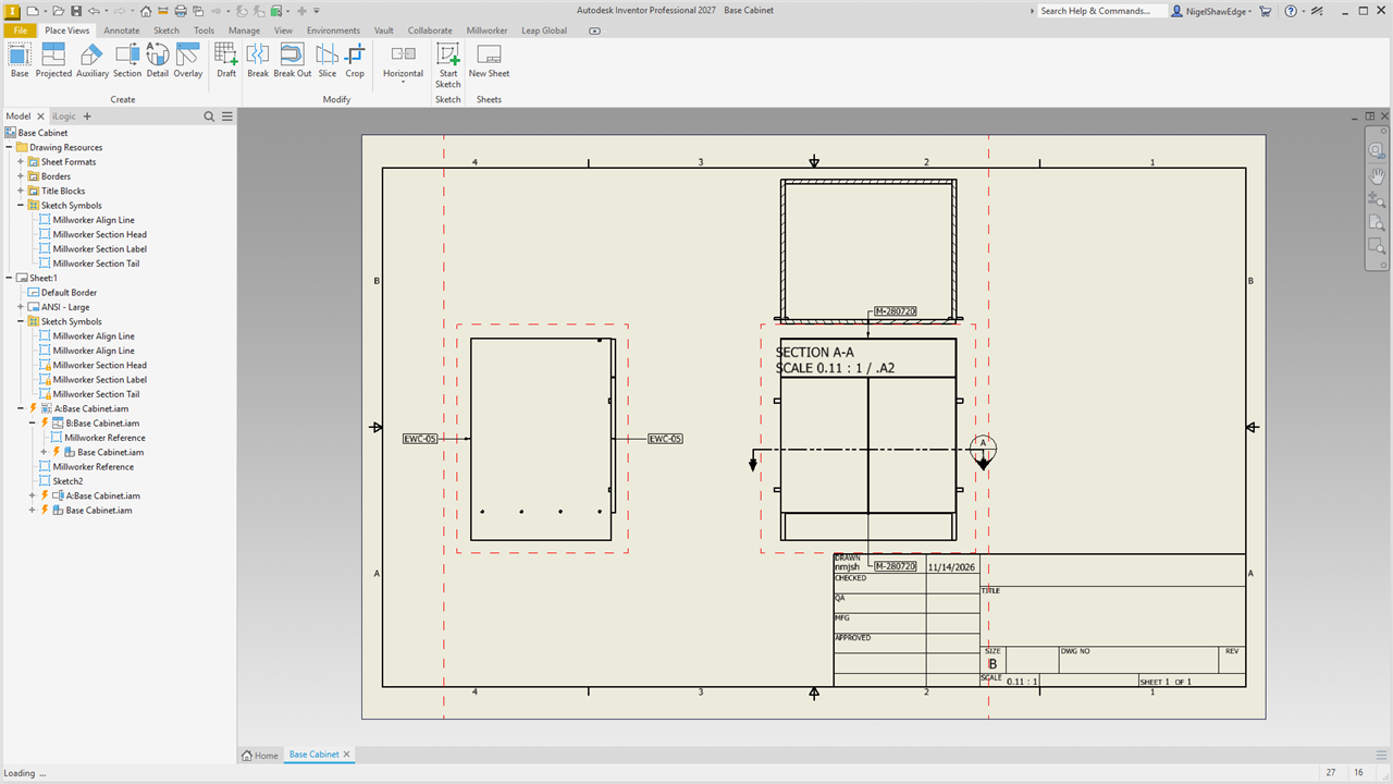
 Update Labels
Re-letter every section and detail from sheet 1, and name views FRONT VIEW, SIDE VIEW, PLAN VIEW.
- Any drawing. Millworker tab → Sheets panel → Update Labels.
Every change is listed before anything happens; untick any you want left. The lot is one undo step.
- Re-letter sections & details: numbered through the drawing from sheet 1, so a section added to an early sheet later still comes out as A. Choose letters (A, B … Z, AA) or numbers, and whether each sheet runs top-left first or in the order the views were made. Leaving one out keeps its letter, and the rest run on without a gap or a clash.
- Name views from Settings: base and projected views get the label for the way they look (Front, Top, Left, an iso…) from Millworker Settings, Labels tab. Only the label's first line changes; the scale line stays. Untick it when you don't want view names touched.
- Number views on each sheet: every view with its label shown gets a number in front of its title, 1. FRONT VIEW, 2. SECTION A-A, 3. THIS CUSTOM TITLE, in the sheet's order (top-left first, or the order made); each sheet starts again at 1. Untick it and Update Labels takes the numbers off again, and only the numbers: 1. THIS CUSTOM TITLE becomes THIS CUSTOM TITLE. A section's letter stays live in its title.
Rows already right show No change and can't be ticked. The choices are remembered, and are also in Millworker Settings, Labels tab, under Update Labels does: update view names, letter or number sections and details (SECTION A-A or SECTION 1-1), and number the views on each sheet.
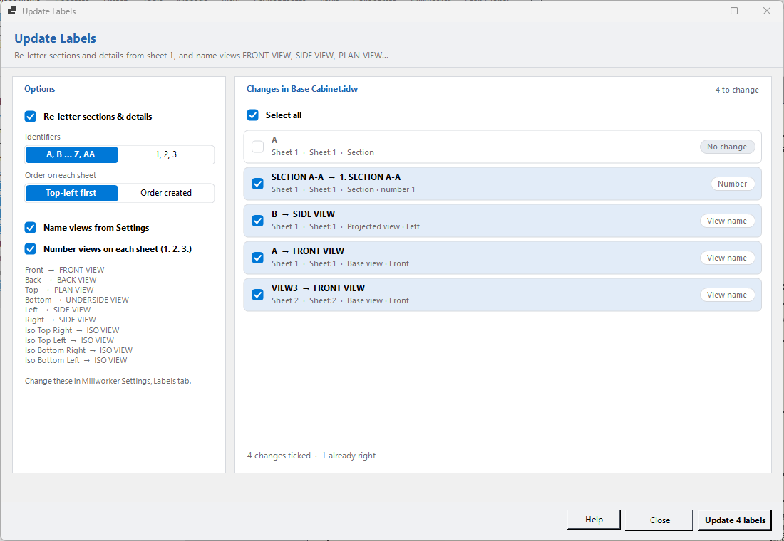
 Reset Labels
Put every view label on the sheet back to its style's own text.
- Any drawing. Millworker tab → Sheets panel → Reset Labels.
Every view label on the active sheet goes back to its style's own text (Inventor's Restore view label), in one undo step. Typed titles and numbers go; Update Labels names and numbers them again.
 Grey Sections
Every section hatch on the sheet solid light grey.
- Any drawing. Millworker tab → Sheets panel → Grey Sections.
Every hatch in the views on the active sheet becomes solid light grey (RGB 211, 211, 211), no longer by material, in one undo step. The status bar says how many.
 Copy Sheets
Copy sheets with a different model on each copy; the originals stay as they are.
- Any drawing. Millworker tab → Sheets panel → Copy Sheets.
- Tick a sheet.
- Click its new-model box (or the … button) and choose the model, assembly or presentation its copy should show.
- Press Copy.
Each copy goes at the end of the drawing with its views showing the new model: dimensions, notes and layout come across from the original. The original sheets are never changed. A ticked sheet with no new model chosen isn't copied. Rows show how each copy went; a model that isn't a copy of the original can't always be swapped.
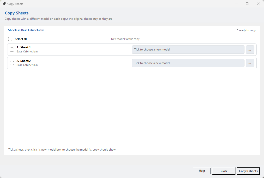
 Drawing Builder
A full drawing set from an assembly: one sheet per model, laid out by your sheet layouts.
- A saved assembly. Millworker tab → Drawing panel → Drawing Builder.
The list holds the top assembly, every sub-assembly and every part (Content Center and library parts are left out), with how many times each is used. Tick the ones that get a sheet, or use the quick select: All, Assemblies, Parts or Flats (sheet metal with a flat pattern, and wood flat panels). Change a tick and it becomes a custom selection. Models with a drawing already open start unticked.
Sheets, in this order: the list on the right shows the sheets the set makes. They are set once in Settings, Sheets tab: which layouts are ticked for the Drawing Builder, what each is for, and their order. There is nothing to pick here. The set goes down that list: every ticked model the first layout is for, then every model the second layout is for, and so on. A model gets one sheet for each layout that is for it. Rest the pointer on a sheet to see its layout.
- A model's first sheet is named by its part number; a further sheet adds the layout's name.
- Sheet metal uses the Parts layouts when there is no Sheet metal layout.
- A layout with only flat pattern boxes is used only for sheet metal with a flat pattern (and wood flat panels). Flats keeps to those layouts when there are any.
Build makes a new drawing from the template in Settings. A part (or sheet metal part) is drawn from its own shape, not the way it sits in its model: its largest flat face is the front, turned so the face's longest edge runs across (always landscape), and plan, side and iso follow from that. Each view group (a base view and the views projected from it) is placed in its boxes and given the largest standard scale that fits them all (1:2, 1:3, 1:4, 1:6, 1:8, 1:12, 1:16…; untick Round each view group down to a standard scale on the Sheets tab to fill the boxes exactly); sheet metal gets its flat pattern. The drawing is left open, not saved.
- A view set to hide its label is placed without one.
- An edge view (Front Right edge and so on) or a view with Look down gets its own camera: the front turned to the edge, then looked down on. The views projected from it follow it. A part keeps its largest face as the front, and a sub-assembly stands as in the top assembly.
- A Perspective view is made again on its own, looking the same way, after its group is placed. Nothing can be projected from it, so a view projected from it is placed on its own, still orthographic. A flat pattern is always orthographic.
- A layout's parts list box gives an assembly sheet a parts list, made from the sheet's first view. Its revision table box gives the sheet a revision table, for that sheet or the whole drawing, numbered and with its first row filled in.
- Anything that can't be done (a view that can't be aimed, say) is done the plain way and listed at the end. Each sheet, view and table placed is written to
drawing-builder.login Millworker's data folder.
Sub-assemblies are drawn as they stand in the top assembly. A CabinetCAD cabinet is built lying in its own file (Z up) and stood up in the list's assembly, so its sheet's front, plan and side are taken from the top assembly's own front, top and right where the cabinet stands there, not from the cabinet's file. Sub-assemblies that are the same (the same parts, the same sizes, in the same places), such as three identical cabinets each in its own file, get one sheet: the list shows the first with × 3 · also C2, C3.
Main assembly: the top assembly gets a sheet from every layout Used for Main assembly, in list order: the starters give it a front page and then a general elevation.
Wood flat panels: a curved panel flattened with Make Flat is listed as Curved panel · wood flat ✓ and gets a layout made for Wood flat panels (the starter has its front, side, iso and a flat pattern box with overall sizes). The flat pattern box shows the panel's wood flat. With no such layout, the Sheet metal layouts are used, then the Parts layouts. Flats in the quick select picks sheet metal and wood flat panels.
Order under each layout: the models come in the component list's order. Drag a row up or down (a blue line shows where it goes), or click a row and move it with ▲ and ▼.
Sheet layouts
In Millworker Settings, Sheets tab: the drawing template (borders and title blocks come from it; Inventor 2027 has its own, first set to Standard - 2027.idw in the EdgeVault templates folder) and the sheet layouts. Each layout has a size (ANSI B 17×11, C, D, or A4 to A0, landscape), what it's Used for (Main assembly, Sub-assemblies, Parts, Sheet metal or Wood flat panels), its title block and border from the template (or the template's own, or none) and its boxes. The thumbnail shows the template's real sheet under the boxes; the line under it sums the layout up, such as 2 view(s) · parts list · revision table (sheet).
Sheet order: the layout list is the order of the sheets in the drawing set. Drag a layout up or down (a line shows where it goes), or move it with ▲ and ▼; each row shows its place. Several layouts can be for the same thing: each makes its own sheet, in list order. New copies the picked layout, so a variation is quick to make.
Tick = used by Drawing Builder: untick a layout you keep but rarely use. It stays in Settings, marked not in builder.
Edit layout… (or double-click) opens the editor: add base views (any ViewCube direction, an edge view, or the flat pattern) and projected views; drag them to move, drag sides and corners to size. For the picked view:
- Show the view label: whether its label is on the sheet. A box without one says (no label).
- Add overall dimensions: its overall width (above) and height (to the right). Not on a perspective, edge or look-down view. The starter layouts have them on the front, plan, side and flat pattern views.
- Orthographic or Perspective, set on each view. A flat pattern, and a view projected from one, stays orthographic.
- The edge views (Front Right edge, Front Left edge, Back Right edge, Back Left edge) are the ViewCube's upright edges, level between two faces.
- Look down (0° to 25° in 5° steps) raises the eye so the top shows. Base views only; not for a flat pattern.
- The little cube in the picked base view's box shows how the view will look.
A projected view snaps in line with its parent beside, above or below it, or goes at a corner for an iso. Everything snaps to 5 mm. Until you save layouts of your own, the starter layouts (all B, 17×11) are used.
Parts list and revision table: + Parts list and + Revision table put a box for each on the sheet (blue and violet), one of each per layout. A parts list only goes on a Main assembly or Sub-assemblies layout. Drag the box where the table goes. Pick it to set:
- Style: from the template's styles, or the template's default.
- Snap tables to the border (on at first): the box snaps to the border's inner line (inside any zone strip, below a header strip) and to the top of the title block, and the real table goes tight against it on the side its box is nearest. Off, the table goes at its box.
- Revision table for Sheet (each sheet has its own) or Drawing (one for the whole drawing).
- Numbering (A, B, C or 1, 2, 3) and the first row description (FIRST ISSUE at first), put in the Description column. These two are shared by every layout.
The real table's size comes from the model, so the box only says where it goes: the table takes the corner of its box nearest the sheet's corner.
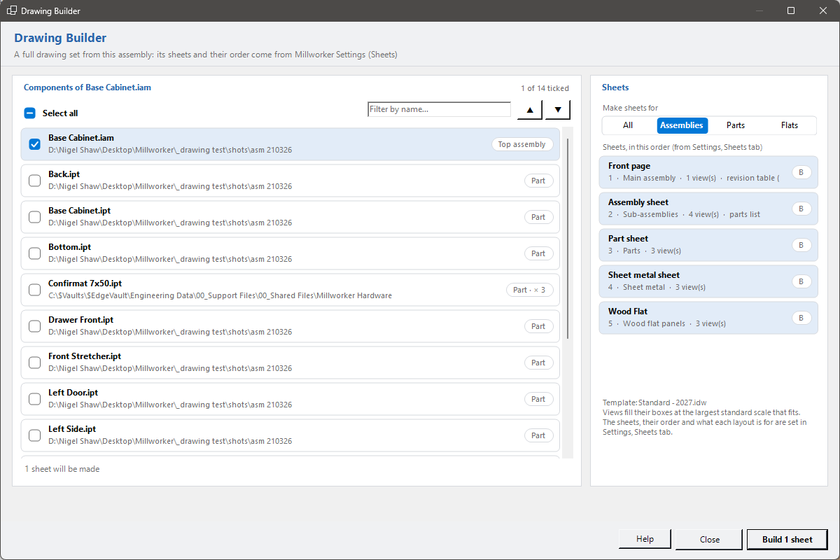
 Sheet Names
Rename every sheet from the model on it: description, part number, job number.
- Any drawing. Millworker tab → Sheets panel → Sheet Names.
Each sheet is named from the model of its base view. Click the parts of the name in the order they go (Description, Part number, Job number; each shows its place) and set what goes between them. Every rename is listed first; untick any to leave. The lot is one undo step.
The job number is the model's Project Number iProperty, else its Project iProperty, else the leading digits of its file name. The default format is in Millworker Settings, Sheets tab; tick Use as the default here to keep a change. A sheet index follows the new names.
 Sheet Table
A sheet index (number and title of every sheet) that keeps itself up to date.
- Any drawing. Millworker tab → Sheets panel → Sheet Table.
Places a SHEET INDEX table near the top-left of the active sheet: a row per sheet with its number and title (the sheet's name). Drag it where it should go. When sheets are added, removed, moved or renamed, the table follows a moment later. There can be one on several sheets; each keeps up.
 Reference Tables
The project's MatFin workbook as front page tables: general notes, client refs, finishes, materials, layups, hardware.
- Any drawing. Millworker tab → Sheets panel → Reference Tables.
Each project keeps one MatFin workbook (for example 261234_MatFin.xlsx) in its project folder, the first folder under the projects root (C:\$Vaults\$EdgeVault\Engineering Data\PROJECT). Its MATFIN sheet is one list, a row per item: EWC CODE, CLIENT CODE, DESCRIPTION, TYPE, SUB TYPE (wood, glass, metal...), INNERGY SKU, and for layups CORE, FACE 1, FACE 2. General notes are the top rows (a description only); everything else is added at the bottom. TYPE is the filter: GENERAL NOTE, FINISH, MATERIAL, LAYUP, HARDWARE, PURCHASED.
The drawings only call out the EWC code. Finishes (paint, laminate...) and materials (core, metal, glass, lumber, edgebands, and veneers: sub type VENEER, numbered VEN01...) are kept apart; a layup puts them together, for example PAN01 = WUD03 + VEN01 + VEN02 (a core and two veneer faces). The client's codes are mapped to ours in the CLIENT CODE column, never used directly.
- Pick a group at the top: General notes, Client Ref Mapping, Finishes, Materials, Layups, Hardware, and Panels, Metal, Glass (materials by sub type) and Purchased when they're turned on with Optional tables (beside the groups; also in Settings, References tab): Panels takes sheet goods (a sub type with panel, sheet, MDF, HDF, ply, particleboard, melamine or OSB in it).
- Tick a row's box to show it on the front page. The rows the front page's tables already show start ticked; nothing else does. Rows whose code is used by a part in the drawing are marked In drawing. Client Ref Mapping lists every row (those with a client code first) to search and pick from. Untick Use table to leave a group's table off the front page: its rows stay ticked (kept with the drawing) for when you turn it back on.
- Click a row (anywhere but its tick box or Edit) to see it in Row info on the right, only the fields its type has. Edit, on the row or under Row info, opens it in a window of its own; + New row, under the list, opens that window empty for the tab you are on (the next free code of its kind filled in). Save in that window writes that row, and only it, to the workbook at once (a note goes after the other notes, everything else at the bottom); Cancel leaves it as it was. To take a row out (a layup too), click it and press Remove row: it says first which layups are made from it and whether the drawing uses it; Save, at the bottom right, then deletes it from the workbook.
- Press Update tables: on sheet 1 (the front page) each group with ticked rows gets its table, a group with none ticked (or with Use table off) loses its table, and all of them are stacked down from the top right of the border, in group order.
Layups are made in the assembly (Push to MatFin, Layups tab) and put on parts with Tag Layups: here they're listed and placed in the Layups table, but not added or changed.
Which workbook: the one in the drawing's project folder (the first folder under the projects root), found again each time you open the window, so moving to another project's drawing finds that project's workbook. One picked with Browse is kept only for drawings in its own project. New workbook starts one in the project folder from your template: a MatFin workbook with the general notes and the codes every job uses (set in Settings, References tab, or with Choose… the first time). Its rows are listed ticked; untick any you don't want, or start from another project's workbook, the Material Manager, or an empty one. Vault users are warned to check Vault first, so a project never ends up with two. Add rows from… copies more rows in later, from the template or another workbook: rows it has already (the same code, or a note with the same words) are shown but not added again.
Checks: an EWC code can only be used once. One typed in Row info that another row has already goes red, and the status line says whose it is; Save refuses it, and the sheet is checked again as it's written, so a code someone else added meanwhile is caught too (then nothing is saved). Codes used twice in the sheet itself (typed in Excel) are flagged when the workbook is read. A row needs a description, and every row but a note an EWC code.
Look up: for finishes (PLAM and the like), materials, hardware and purchased items, Row info has a lookup under the description. Material Manager lists its materials, PLAMs, veneers, finishes and edgebands: double-click one to fill the type, sub type, description and INNERGY code. INNERGY shows only when Use INNERGY is ticked in Millworker Settings, References tab, with your email and API key: double-click a result and the SKU goes in its column and INNERGY's name is added to the description. With it unticked, everything works from the Material Manager.
Codes and the Material Manager: each project numbers its own codes (Black Mel 2S can be WUD01 on one job, WUD04 on another). The INNERGY SKU links them: a Material Manager material, PLAM or finish whose INNERGY code is a row's SKU takes that row's code in this project; one with no INNERGY code links by name (the row's description is the material's name, as rows added from the Material Manager are). Assigning it puts that code on the parts, the Material and Finish callouts show it, and Push to MatFin lists it for layups. The Material Manager's Default code is never used: it shows in the DEFAULT CODE column for reference, and a material with no row here has no code until it gets one. To add rows for the materials a job uses, press Add rows from… and pick Material Manager: tick them, and each gets the next free code of its kind with its SKU. Update part codes (at the bottom) gives the drawing's parts this project's codes (their material, and the finishes on their faces) after the workbook changes: it lists each change to confirm, the parts that are read-only, and the materials not in the workbook yet. Then save the parts.
Vault: for Vault users (Settings, References tab, I use Vault; on by default). A checked-in workbook is read-only. It's read as it is, but before anything is written you're asked to check it out in Vault (then Retry). Check it back in when you're done. If someone has it open, you're told to close it there first. Without Vault the same checks are plain file checks: read-only, or not there.
No workbook, or the old one: when the project folder has none, you can make a new one there. A workbook in the old layout (sections headed ###) can be copied into a new one beside it: laminates, veneers, edgebanding, paint and upholstery become finishes, panels, metal, glass and lumber materials, the old TYPE the sub type, and M-numbers the INNERGY SKU. The old workbook is left as it is. A new workbook is a new file: add it to Vault.
Table styles: the schedules keep the eight column positions the EWC styles are made for (CODE, TYPE, NUMBER, DESCRIPTION...), with the sub type as TYPE and the INNERGY SKU as NUMBER. By default General notes uses EWC - 0. GENERAL TABLE, Finishes 1. FINISH TABLE, Materials and Panels 2. MATERIAL TABLE, Hardware 3. HARDWARE TABLE, Purchased 4. ELECTRICAL TABLE, Glass 5. GLASS TABLE and Metal 6. METAL TABLE. Client Ref Mapping (CLIENT CODE, EWC CODE, DESCRIPTION) and Layups (EWC CODE, CORE, FACE 1, FACE 2, DESCRIPTION) keep their own columns whatever the style. Pick others in Settings, References tab.
 Sheet Refs
Write each model's sheet numbers into its MillworkerSheetRef iProperty, for parts lists.
- Any drawing. Millworker tab → Sheets panel → Sheet Refs.
Every part and assembly shown in the drawing's views gets the numbers of the sheets it is on in its custom iProperty MillworkerSheetRef: 3, or 1, 4, 6, 7 when it is on several. Add that iProperty as a column in a parts list to show where each part is detailed. Save the models to keep it; locked (checked-in) models are listed and left. Run it again after adding or moving sheets.
 Update Mass
iProperties, Physical, Update for every part and assembly: quick, or rebuild and save.
- Drawing: Sheets panel. Assembly: Drawing panel. Part: Mass panel.
Quick update works out the mass of every part and assembly in memory so parts lists and title blocks show it; nothing is saved, so Vault never asks to check files out. Rebuild & save rebuilds every model, updates the mass and saves the files you have checked out; read-only ones are listed (their values are right for this session only).
 Drawing Output
Export PDF, DWG, DXF, BOM, STEP and USDZ from one drawing or every open drawing, named and filed by a profile.
- Drawing: Millworker tab → Output panel. Assembly: Drawing panel.
- Choose Active drawing or All open (tick or untick drawings in the list).
- Pick the profile and tick the outputs: PDF (one combined, or a PDF per sheet), DWG and DXF (a file per sheet, zipped), BOM (Excel, structured, from the first model), STEP and USDZ.
- Choose where: Profile folders (the drawing's folder with the profile's project folder swapped for its output folder, or next to the drawing when the profile has none) or My folder, with a sub-folder per drawing if you like.
- Press Export.
Update mass first runs a quick mass update (nothing saved) before each drawing. Rebuild & save mass is the full update, which may ask to check files out. Each drawing's row shows how it went; the sheet names are always put back afterwards. The outputs ticked, where to save and the options are remembered for you, per profile.
Profiles
In Millworker Settings, Output tab. Two to start: Millworker and Personal; add, copy or delete more. Each holds the file names (tokens: model <PartNum> <Desc> <RevNum>, drawing <dwgPartNum> <dwgDesc> <dwgRevNum>, sheet <shtNum> <shtRevNum> <sht1RevNum>, and the day of the export <Date>), the names the sheets take in the PDF, underscores for spaces, letter or number revisions, the project and output folders, the DWG and DXF INI files, and the outputs ticked the first time someone uses it.
Name Builder
Each name has a … button that opens the Name Builder. The name shows as chips: a name part is a coloured chip with its friendly name, text between parts is a plain chip, and each has an × to take it out. Click a chip to put the next part before or after it; Backspace, Delete and the arrow keys work too. Add the parts, separators (underscore, hyphen, space, spaced hyphen, dot) and your own text, and the example underneath shows the name it makes. A part the export doesn't know shows amber and stays as typed.
Date adds the day of the export in the format picked: 26.11.18 (yy.MM.dd, the shop's), 2026-11-18 (ISO 8601), 20261118, 261118, 2026.11.18, 11-18-2026 and 11.18.26 (US), 111826, 18-11-2026 and 18.11.26 (UK / EU), 18 Nov 2026 or Nov 18 2026. In a name it is <Date> (yy.MM.dd) or <Date:yyyy-MM-dd> for another format. Formats with slashes aren't offered: a file name can't hold them.
 Show and Clear Mark Types
Doors' and drawers' opening lines and hinge holes, drawn from the parts marked with Cabinet Marker.
- A drawing of an assembly whose parts are marked with Cabinet Marker.
- Mark Types panel → Show Mark Types or Clear Mark Types.
- Show Mark Types: click a view. Each marked door gets dashed lines from its far corners to the middle of its hinge side; drawer fronts get them pointing down. The hinge cups and their screw holes are drawn through as thin circles.
- Click more views, or Esc to finish. Clicking a view again draws its marks afresh (after the model changed).
- Clear Mark Types: click views to take their marks off.
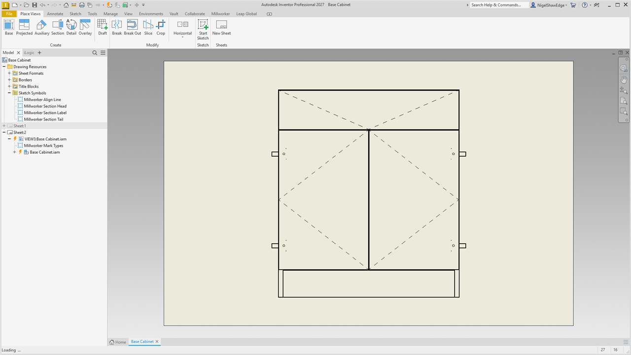
The hinge side is the one the door is marked with (its type's side in Settings, Cabinet marks). A view of the door's back (the face its hinge cups are drilled in toward you) swaps left and right, as you'd see it. When a door's hinge cups are on another side than its mark, it's still drawn as marked, and the status bar names it so you can check the model. Parts seen edge-on in the view are left out.
The lines go in a sketch of the view, so they move with it. They're tagged (attribute set Millworker.MarkTypes) so Clear Mark Types finds them.
 AutoDim
Dimension a cabinet view's doors and drawer fronts, or one panel, the shop's way.
- A drawing of an assembly whose doors and drawer fronts are marked with Cabinet Marker (for a whole view). Any view for a single panel.
- Mark Types panel → AutoDim.
- A small window chooses what a view gets: each door and drawer front (its width across its middle and its height near its right side, inside it), the overall width (above the view) and height (at its left), and the height of each level chained at the left (top, each row of fronts, the toe kick). Gap from the view sets how far out the outside dimensions go. Press Pick views or panels.
- Click a view's frame: it's dimensioned as chosen.
- Or click a line of a panel: that one panel gets its width and height, inside it.
- Click more, or Esc to finish. Each click is one undo step.
The dimensions are ordinary Inventor dimensions in the sheet's dimension style, tied to the panels' edges, so they follow the model. Doors and drawer fronts seen edge-on are left out. The choices are kept for the Inventor session.
 Show Flat
Place the flat of a curved panel (Make Flat) or a sheet metal part from the models on this sheet.
- A drawing whose views show curved panels flattened with Make Flat, or sheet metal parts with a flat pattern.
- Mark Types panel → Show Flat.
- The window lists the flats of every model in this sheet's views: wood flats and sheet metal flat patterns, each with its size.
- Tick the ones you want and press Place.
- Click on the sheet where each goes. It's placed at the scale of the view its panel was found in, named <panel> FLAT.
The Drawing Builder places wood flats by itself: a curved panel with a wood flat gets a Wood flat panels layout, whose flat pattern box shows its flat.